Sansui AU 888 Brochure

This is the 2 pages manual for Sansui AU 888 Brochure.
Read or download the pdf for free. If you want to contribute, please mail your pdfs to info@audioservicemanuals.com.

Page: 1 / 2
left right
Sansui AU 888 Brochure

Extracted text from Sansui AU 888 Brochure (Ocr-read)


Page 1

SnAKEI

_~u mm
. nun-nun .

mls p-rqus-fi ,
mu

0 j;

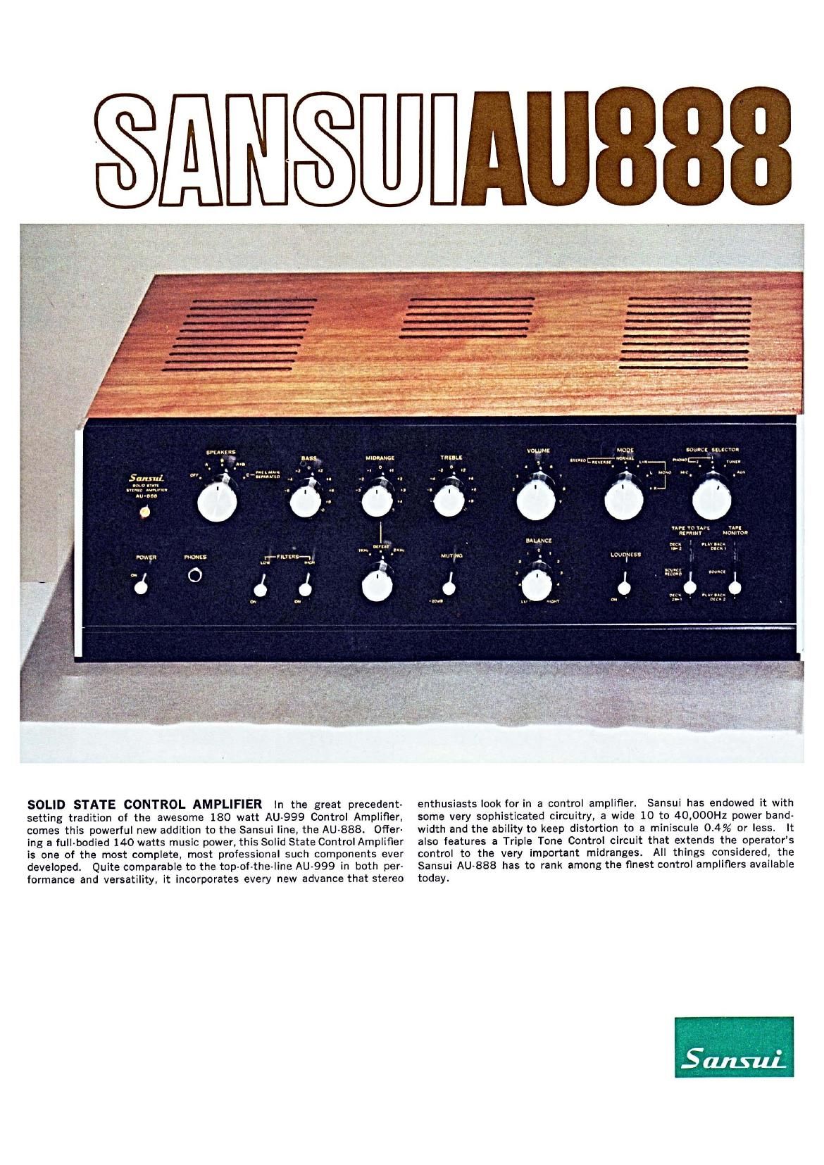
SOLID STATE CONTROL AMPLIFIER In the great precedent-
setting tradition of the awesome 180 watt AU-999 Control Amplifier,
comes this powerful new addition to the Sansui line, the AU-888. Ofier-
ing a full-bodied 140 watts music power, this Solid State Control Amplifier
is one of the most complete, most professional such components ever
developed. Quite comparable to the top-of-the-line AU-999 in both per-
formance and versatility, it incorporates every new advance that stereo

W
m
m-
m
m
m

09
I'IIILE
""° C mun m? m

c . S n
-. u '
. ,9
.. * u , r \
_, u a n
. a u

LWDrESS

é

enthusiasts look for in a control amplifier.

5-.- T .. W7W,,,HWWWWW,~ cu- ..-mm m .

llllllllll

_. A_...t1....§-5

IOUICI um: ro-

l
ME: . um"
. . .

url to un YAPI
klrnmr Momma

Nu ' unnu-
iD-l mm

Ion-ct .
. name I M l
m... _ mum.
a-- mu: '

Sansui has endowed it with

some very sophisticated circuitry, a wide 10 to 40,000Hz power band-
width and the ability to keep distortion to a miniscule 0.4% or less. It

also features a Triple Tone Control circuit
control to the very important midranges.

that extends the operators
All things considered, the

Sansui AU-888 has to rank among the finest control amplifiers available

today.

Page 2

DIRECT-COUPLED POWER AMPLIFIER: The
power amplifier section has direct-coupled a
two-stage difierential amplifier and a semi-
complementary Darlington circuit. Stripped of
conventional output capacitors, the AU-888 in-
stead employs two-plus and minus-power
supplies for its output stage. Since all stages
are direct-coupled, negative feedback is uniform-
ly applied throughout the entire audio frequency
range and down through deep lows to D.C. This
in turn has helped improve the amplifier's damp-
ing factor and output characteristic at very low
frequencies, reducing intermodulation distortion
to an unprecedentedly low level.

HIGH POWER OUTPUT: High power output-
music power of 140 watts at 4 ohms, and con-
tinuous power of 50 watts per channel at 4 ohms
and 45 watts per channel at 8 ohms-and low
distortion-total harmonic distortion and inter-
modulation of less than 0.4% each-characterize
the AU-888. Its power bandwidth stretches from
10 to 40,000Hz(8.0). This means that sound
is reproduced with ample reserve power from
very low to very high frequencies.

LOW-NOISE PREAMPLIFIER SECTION:The
use of carefully selected quality PNP silicon
transistors in the preamplifier section results
in an unprecedentedly low noise level, greatly
improved transparency of the faintest pianis-
simo notes, and a substantially extended dy-
namic range.

NO ELECTROLYTIC COUPLING CAPACI-
TORS: The AU-888 utilizes direct-coupled
circuitry wherever possible. Where coupling
capacitors are considered absolutely necessary,
circuit impedance has been raised and Mylar
capacitors have been employed for an improved
frequency response at high frequencies.
PERFECT PROTECTION CIRCUIT: The AU-
888 employs extra transistors exclusively for the
purpose of temperature compensation, and in-
corporates a special difierential amplifier stabi-
lizing circuit' (patent pending) to stabilize its
two-stage differential amplifier.

In addition, six quick-acting fuses are included
to give the power transistors further protection
in the unlikely event of an overcurrent. In addi-
tion a special speaker protection circuit em-
ploying an SCR has been newly adopted in
the AU-888, so that your valuable speakers are
protected in multiple ways.

SPECIFICATION

POWER AMPLIFIER SECTION
POWER OUTPUT

MUSIC POWER(IHF) 140W at Mt
100W at 8!!
CONTINUOUS POWER 50!50W at 4:2

45/45W at an
TOTAL HARMONIC DISTORTION
less than 0.4% at rated outDUt
INTERMODULATION DISTORTION (60Hz: 7,000Hz
=4:l SMPTE method)
less than 0.4% at rated output
POWER BANDWIDTH (IHF) 10-40,000Hz at 8&2
FREQUENCY RESPONSE (at normal listening level)
10-70,000Hz tldB
CHANNEL SEPARATION (at 1,000Hz, rated output)
better than 50dB
better than 100dB
IV for rated outp ut
50kt!

HUM AND NOISE (IHF)
INPUT SENSITIVITY
INPUT IMPEDANCE

LOAD IMPEDANCE 4-169
DAMPING FACTOR 20 at 8!)
PREAMPLIFIER SECTION
OUTPUT VOLTAGE
MAXIMUM OUTPUT VOLTAGE 4V
RATED OUTPUT VOLTAGE 1V

TOTAL HARMONIC DISTORTION
less than 0.1% at rated
output voltage

SANSUI ELECTRIC CO., LTD. 14-1. 2-CHOME, IZUMI, SUGINAMl-KU. TOKYO 168, JAPAN/TELEPHONE: 323-1111/TELEX: 2322076
SANSUI ELECTRONICS CORPORATION 32-17 618T STREET, WOODSIDE, NEW YORK 11377, U.S.A./TELEX: NEW YORK 422633 SEC UI
SANSUI AUDIO EUROPE S.A. DIACEM BUILDING, VESTINGSTRAAT 53-55, 2000 ANTWERP, BELGIUM/TELEX: ANTWERP 33538

" nan-m-mm-mm... ' '

TRIPLE TONE CONTROL SYSTEM: Based on
the idea that variable equalizers are needed to
enable truly accurate reproduction, Sansui has
incorporated a triple tone control system in the
AU-888 which makes use of a midrange tone
control circuit in addition to the regular bass
and treble circuits. It provideds for more ac-
curate compensation of the room acoustics and
any irregularities in program sources.
SEPARABLE PRE- AND POWER AMPLIFIER
SECTIONS: With the Speaker Selector set at
the "C" position, the preamplifier and power
amplifier sections of the AU-888 can be utilized
separately to achieve an advanced electronic
crossover stereo format in which separate power
amplifiers drive the tweeter, midrange and
woofer.

PERMITS USE OF TWO TAPE DECKS: Two
tape decks can be connected to the AU-888.
Recordings can be made by either, or by both at
the same time, and monitored as they are made.
A newly adopted TAPE-TO-TAPE REPRINT cir-
cuit permits a recorded tape to be reprinted
from one tape deck to the other. And the amaz-
ing thing is, you can listen to a radio broadcast,
a disc or any other program source while the re-
printing is being accomplished.

POWERS THREE SETS OF SPEAKER SYS-
TEMS: The AU-888 is capable of connecting
up to three sets of speaker systems, one of
which can be employed in an electronic cross-
over stereo system, allowing comparisons to be
made between regular stereo system and ECS
system.

TONE SELECTOR FOR THE MIDRANGES:
The midrange Tone Control is provided with a
special Tone Selector circuit that permits defeat-
ing a particular tone control circuit or chang-
ing the vital control frequency between two

FREQUENCY RESPONSE 15-50,000Hz +0.5dB
-l.5dB
HUM AND NOISE (IHF)
PHONO-l AND 2
MIC
TUNER AND AUX
INPUT SENSITIVITY

(at 1.000Hz, rated output voltage)

better than 80dB
better than 80dB
better than 85dB

PHONO-l 2mV(50kn)

PHONO-2 2mV(30k.50k,100kfl)
MIC 2mV (50kfl)

TUNER 180mV(100kn)

AUX 180mV (100kn)

TAPE MON (pin) 180mV(109kD)

TAPE MON (DIN)
RECORDING OUTPUT

lBOmV (100k (2)

TAPE REC (pin) IBOmV
TAPE RECORDER (DIN) 30mV
EQUALIZER PHONO, MIC NF type
CONTROLS
BASS +12dB -8dB at 20H:
MlDRANGE +5dB -5d Bat 1.000Hz or
2,000Hz
TREBLE +12dB-8dB at 20,000Hz
TONE SELECTOR
MlDRANGE 1,000Hz/DEFEATI2,000HZ
LOUDNESS +8dBat 50Hz

+ 3dB at 10.000Hz

frequencies.
now possible.
RIPPLE FILTER POWER SUPPY CIRCUITS:
The plus and minus power supplies of the power
amplifier, as well as the power supply for the
preamplifier, are all equipped with a separate
ripple filter circuit, which completely shuts out
detrimentalhum and promotes true hi-fi repro-
duction. The result, of course, is completely
stabilized power supplies.

Two PHONOGRAPH INPUTS: The AU-888 is

equipped with two phonograph input circuits;

PHONO-l circuit has an input impedance of

50m, while the input circuit of the PHON0-2

can be switched over among 30kt), 50m and
100k!) to match the load resistance, the car-
tridge or the operators preference of timbre.

Together, the two circuits permit comparing two

cartridges or phonographs for better timbre or

tonal quality.

COMPLETE ACCESSORY CIRCUITS: The AU-

888 ofiers all the accessory circuits one would

expect to find in a quality, advanced control

amplifier:

1) DIN connector to simplify the connection of
a tape recorder or deck.

2) Sharp cutting, negative feedback type high
and low filter circuits.

3) Loudness control circuit.

4) Microphone input jack that accepts a stand-
ard phone plug.

5) Headphone jack for private listening.

6) Mode Selector control with STEREO-REV,
STEREO-NORM, MONO-L+R, MONO-L,
and MONO-R positions.

7) Foolproof, one-touch speaker output termi-
nals.

8) Muting Switch which temporarily attenuates
sound by 20dB.

Finer control of the midranges is

SWITCHES
LOW FILTER -8dB at 50H:
(12dB/oct. NF type)
HIGH FILTER -8dBat10,000Hz
(lZdB/oct.. NF type)
MUTING -20dB
MODE STEREO-REVISTEREO-

NORM/MONO-L+R,
MONO-L/MONO-R
MIC/PHONO-Z/PHONO~1/
TU NER/AUX

PLAY BACK DECK-l/
SOURCE/PLAY BACK
DECK-2

DECK-1 to 2/SOURCE
RECORD/DECKrZ to l
OFF/SYSTEM-A/SYSTEM-
B/SYSTEM-A+B/SYSTEM-C

SOURCE SELECTOR

TAPE MONITOR

TAPE TO TAPE REPRINT
SPEAKER SELECTOR

GENERAL
SEMICONDUCTORS
Transistorst41 Diodes: 12 SCR: 2
POWER REQUIREMENTS
POWER CONSUMPTION 4OOVA (max. signal)
POWER VOLTAGE 100/110/117/127/220,
240/250V, 50/60Hz

DIMENSIONS 148mm (5/§")Hx460mm
(18%)Wx305mm (12}I-JD
WEIGHT 7.2 kg (15.8 lbs.)

Printed in Japan (11003K4)