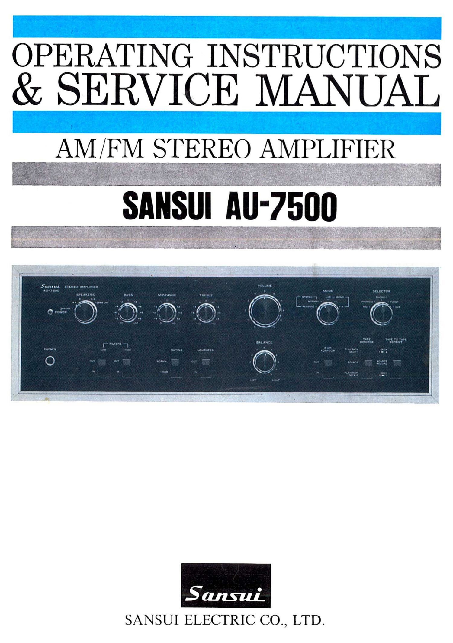
Sansui AU 7500 Owners Manual

This is the 27 pages manual for Sansui AU 7500 Owners Manual.
Read or download the pdf for free. If you want to contribute, please mail your pdfs to info@audioservicemanuals.com.

Page: 1 / 27
left right
Sansui AU 7500 Owners Manual

Extracted text from Sansui AU 7500 Owners Manual (Ocr-read)


Page 2

We are grateful for your choice of the AU-7500 Integrated
Amplifier.

For over a quarter of a century, Sansui has been building hi-fi
audio equipment, and nothing else. Our mission is very old and at
once ever new to us: to bring the reproduced sound closer and
closer to the original.

The AU-7500 now in your hands is one answer from us to this
never-ending quest. It is a product of the cream of sophisticated
modern audio-electronics knowhow, coupled with our long ex-
perience, and as such, we present it to you with our full confidence.
The AU-7500 is a new breed of Sansuis AU series integrated
amplifiers. Its tone quality has been polished and perfected through
an unprecedented number of listening tests in different acoustic
environments. We feel certain that you will like it, but you will
find this out as soon as you play your first record through it.

This manual has been prepared to guide you in operating and
caring for the amplifier correctly, so that you will get the most out
of its built-in high performance and exceptional versatility.

May we suggest that you read it once carefully?

CONTENTS

SWITCHES AND CONTROLS ....................................... 3, 4
SETTING UP YOUR AU-7500/

OPERATING PROCEDURE .................................... 5, 6
RECORDING AND PLAYBACK BY TAPE DECKS ............ 7
UPGRADING YOUR STEREO (4-CHANNEL STEREO

SYSTEM/ELECTRONIC CROSSOVER SYSTEM) ...... 8
SIMPLE MAINTENANCE HINTS/ACCESSORY LIST 9, 10
QUICK CHECK LIST OF SIMPLE MISTAKES .................. 11
SPECIFICATIONS ...................................................... 12
SCHEMATIC DIAGRAM .......................................... 13, 14
NOTES TO SERVICE ENGINEERS ................................. 15
GENERAL TROUBLESHOOTING CHART ..................... 16
DISASSEMBLY PROCEDURE ....................................... 17
ALIGNMENT ............................................................ 18
PRINTED CIRCUIT BOARDS AND PARTS LIST ......... 19~24

OTHER PARTS AND THEIR POSITION ON CHASSIS... 25, 26

Page 5

V'

SELECYOQ

Volume Control

Tape Monitor Switch

The Alf-7500 connects two tape decks at a time.
Set this switch to ILAYBACK DECK-l or
PLAYBACK DECK-2 to reproduce a recorded
tape or monitor a recording as you make it on a
tape deck connected to the amplifier (monitoring
is possible only if the tape deck is equipped with
separate recording and playback heads. Other-
wise, be sure to keep it at S(.)l7RCE.

4-Channel Adaptor Switch

If you connect a .l-channel adaptor to the .\l7-
7500 and make other necessary connections. you
can upgrade this Z-channel stereo amplifier to
hear l-channel stereo sound by pushing this
switch down to IN (refer to page 8').

Balance Control

Set the Mode Switch to MONO L-l-R once and
adjust this control for equal sound volume from
the left and right speaker systems, then return
the switch to STEREO NORA/LAL. If there is a
large difference in the sound volumes from the
two speaker systems even with this control set
near the center, it may be because left and right
output signal levels from the program source com-
ponent (turntable, tuner, tape deck, etc.) are dif-
ferent. Check the component once.

Selector Control

Turn to an appropriate position to hear the de-
sired program source.

MIC: To use microphones (high impedance type
of 10 kilo-ohms or more) plugged into the Mic.
Jacks on the rear.

PHONO-Z, PHONO-l: To play records on a
turntable connected to the lll().\'() 3 or 1 termi-
nals on the rear. The input impedance of the
lHONO-B circuit is adjustable with the rear-panel
lickup Load Switch to match the load impedance
of the cartridge in use.

TUNER: To hear a radio broadcast from a tuner
connected to the TUNER terminals on the rear.
AUX: To reproduce whatever program source
is connected to the AUX terminals on the rear.
(Connect a turntable with a crystal or ceramic
cartridge, the audio outputs of a television, the
playback outputs of a tape recorder, etc. to the
Al TX terminals. 3

Mode Switch

STEREO: The NORMAL position is normal. If
you have connected the left and right speaker
systems in reverse, set this switch to REVERSE
to restore the normal stereo effect without physi-
cally changing the speaker connections.

MONO: Set to L+R, and the monophonic mix-
ture of the left and right channel signals is heard
from both speaker systems. Set to l.(Ril, and
only the left (right) channel signal is heard from
both speaker systems.

Tape-to-Tape Reprint Switch

If you have two tape (leeks connected to the
amplifier, you can copy a recorded tape from one
to the other.

DECK 1 >2: To record from the tape deck
connected to the TAPE DECK-1 terminals on the
rear to the one connected to the TAPE DECK-2
terminals.

DECK 2 b 1: Reverse of the above.

SOURCE RECORD: To record or play on one
tape deck alone. \Vhen neither of the above
procedures is desired, keep the switch in this
position.