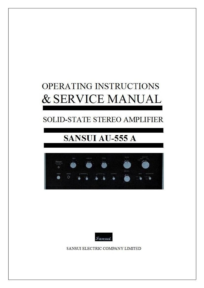
Sansui AU 555A Service Manual

This is the 28 pages manual for Sansui AU 555A Service Manual.
Read or download the pdf for free. If you want to contribute, please mail your pdfs to info@audioservicemanuals.com.

Page: 1 / 28
left right
Sansui AU 555A Service Manual

Extracted text from Sansui AU 555A Service Manual (Ocr-read)


Page 1

OPERATING INSTRUCTIONS
& SERVICE MANUAL

SOLID-STATE STEREO AMPLIFIER

SANSUI AU-555 A

fill/Hui

SANSUI ELECTRIC COMPANY LINIIIED

Page 2

Thank you for selecting the sausui All-555A Solid State Stereo
Control Amplifier, upgraded model of the AU.555, featuring th
refined dull black panels and the exclusive Triple Tone Controls,
We sincerely feel that youve made the best choice possible in
the compact size and medium power amplifier field. In desigi
appearance and preformance. the AU-555A draws heavily on the
careful engineering that has made Sansuis larger All-amplifiers
favorites among stereo enthusiasts throughout the world. Lik
every Sansui audio component, the model ALF-555A was inspectvy
ed and certified to be in perfect operating condition before leav-
ing our factory.

This manual has been prepared to help you keep it that way by
covering the correct procedures for installation. connecting com-
ponents and operating controls. For years of trouble-free stereo
enjoyment, please read it carefully before operating the ampifier.

CONTENTS l
OPERATING INSTRUCTIONS
SWITCHES AND CONTROLS ................................ 3. 4
OPERATIONS .................................................... 5. 6
-SPEAKER CONNECTIONS
-RECORD PLAYING
OPERATIONS .................................................... 7. 8
-RADIO RECEPTIONS
-TAPE PLAYING
ELECTRONIC CROSSOVER SYSTEM ...................... 9. 10
MAINTENANCE .............................................. 11, 12
SPECIFICATIONS / ACCESSORIES ............................ l3
CHARACTERISTICS ............................................ 14
SERVICE MANUAL
TROUBLESHOOTING CHART .. .......................... I5. 16
DISASSEMBLY PROCEDURE/ TEST POINT ................ l7
ALIGNMENT ...................................................... 18
BLOCK DIAGRAM ................................................ 19
PRINTED CIRCUIT BOARDS AND PARTS LIST
........................................ 20, 21. 22, 23. 24
OTHER PARTS AND THEIR POSITION ON CHASSIS
.................................................. 25, 26