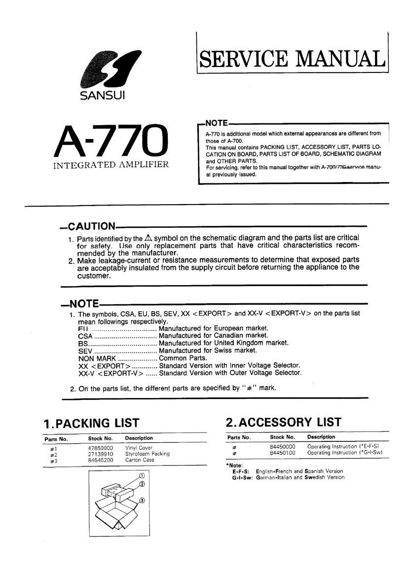
Sansui A 770 Service Manual

This is the 15 pages manual for Sansui A 770 Service Manual.
Read or download the pdf for free. If you want to contribute, please mail your pdfs to info@audioservicemanuals.com.

Page: 1 / 15
left right
Sansui A 770 Service Manual

Extracted text from Sansui A 770 Service Manual (Ocr-read)


Page 1

1 SERVICE MANUALl

SANSUI

NOTE '
A-770 is additional model which external appearances are different from
- those of A-700,
This manual contains PACKING LIST, ACCESSORY LIST, PARTS L0-
CATION ON BOARD. PARTS LIST OF BOARD. SCHEMATIC DIAGRAM
INTEGRATED AMPLIFIER 8 HE PARTS-

For servicing. refer to this manual together with A-7onl73n.:ervica manu-
al previously issued.

-CAUT|ON

1. Parts identified by the A symbol on the schematic diagram and the parts list are critical
for safety. Use only replacement parts that have critical characteristics recom-
mended by the manufacturer.

2. Make Ieakage-current or resistance measurements to determine that exposed parts
are acceptably insulated from the supply circuit before returning the appliance to the
customer.

-NOTE

1. The symbols. CSA, EU. BS, SEV, XX < EXPORT> and XX-V < EXPORT-V> on the parts list
mean followings respectively.
Manufactured for European market.
.. Manufactured for Canadian market.
., Manufactured for United Kingdom market.
.. Manufactured for Swiss market.
.. Common Parts.
.. .. Standard Version with Inner Voltage Selector.
XX-V ...... Standard Version with Outer Voltage Selector.


2. On the parts list, the different parts are specified by "#" mark.

1 .PACKING LIST 2. ACCESSORY LIST

Pam No. Stock No. Description Part: No. Stock No. Dnerlptlon
#1 47859900 Vinyl Cover at 84450000 Operating Instruction ('E-F-SI
#2 271399l0 Styrofoam Packing # 84450100 Operating Instruction ('Grl-Sw)
#3 84545200 Carton Case

Note:
E-F-S: English-French and Spanish Version
G~l-Sw: Germanaltalian and Swedish Versron

Page 2

3. PARTS LOCATION ON BOARD (#F-4769 Input Terminal Board)

Component Side

__J SELE,..

.J"


~s§sss

113332:
F-SOIBA

lrom F-113nr

,57]

0-
s.
"cm F-n13 or
F-SOIS

4. PARTS LIST OF BOARD

-NOTE

1. Some primed circuit boards are not supplied assembled.
To separate these in this service manual, the stock num-
bers are not indicated for these boards. However, stock

3. Abbreviations in this service manual are as follows.

DAbbroviations List

numbers for individual parts are indicated. N-IR- 1 Non-lnflammable RGSiSO'
C.C. : Ceramic Capacitor
2. Since some capacitors and resistors are omitted from parts FC- : Film Capacitor .
lists in this service manual. refer to the Common Parts List 50 1 Eleth'YflC Capacitor _
for capacitors and resistors. which was issued on June 5-3. 3 3"P0'a' E"3<3"°lYC Capacrtor
1987.
4-1. F-4769 Input Terminal Board (#Stock No. 01093201)
Parts No. Stock No. Descriptlon Parts No. Stock No. Descriptlon
OZener Diode #nOd 48172300 DTAH4
sz3 46100900 05Z5 17X # or 46923300 DTA124
or 46101000 0525 LY # or 48229700 DTAI l4
'Transistor AmRS 46229700 3909 1,2W N I R
#nO1 48172300 DTA114
if or 46923300 DTA124 'IC
# or 48229700 DTAi 14 O|C4 46255000 LC40663H
#HQZ 48172300 DTAV 14 or 48056800 LC4966
# or 46923300 DTA124
309 or 48229700 DTA1 14 056 46670600 Push SW , DECK SELECTOR
#nQ3 48172300 DTA1 14
# or 46923300 DTA124 023 46546800 60 Terminal Board, TAPE-1
# or 48229700 DTA114 iPLAYl, TAPE-2
026 46371500 40 Terminal Board, CDAUX

TAPEv {REC}