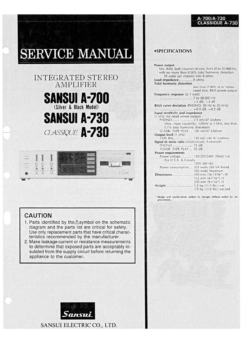
Sansui A 730 Classique Service Manual

This is the 13 pages manual for Sansui A 730 Classique Service Manual.
Read or download the pdf for free. If you want to contribute, please mail your pdfs to info@audioservicemanuals.com.

Page: 1 / 13
left right
Sansui A 730 Classique Service Manual

Extracted text from Sansui A 730 Classique Service Manual (Ocr-read)


Page 1

SERV CE MANUAL

INTEGRATED STEREO
AMPLIFIER

SANSUI A700

(Silver & Black Model)

SANSIJI ll-730
CLASS/QUE N730

CAUTION

1. Parts identified by theAsymbol on the schematic
diagram and the parts list are critical for safety.
Use only replacement parts that have critical charac-
teristics recommended by the manufacturer.

2 Make leakage-current or resistance measurements
to determine that exposed parts are acceptably in-
sulated from the supply circuit before returning the
appliance to the customer.

Saturn].
SANSUI ELECTRIC CO., LTD.

CIA-730

'SPECIFICATIONS

Power output
Min. RMS, both channels driven, from 2010 20,000 l lz,
\Vllh no more than 000% total harmonic distortion
55 watts per channel into 8 ohms
Load impedancm. I , .t 8 ohms
Total harmonic distortion
. less than 0.0 0 at or bolou
rated min. RMS power output
Frequency response (at 1 watt)
............................ I 5 to 60,000 HZ
1 dB, -»2 dB
RIAA curve deviation lPllOiNO 20 Hz to 20 kHz]
,. .oOSdB ADSdB
Input sensitivity and impedance
1 kHz rnr rated hotter output)
PHONO ...... ., . 2.5 me"? kiiohms
(Max. Input capabilm llOmV at l kHz lQaH than
Oi n total harmonic distortion}
TL \ER TAPE PLAY. lSO m\':'47 k lohms
Output level !i kHz:

l-Ul, KtL ,,,,, Ht) m\ inIO 4/ klluhms
Signal to n ratio lshmt» rrurt, Nnottmrki
PHO\().. 1 dB

TL\[K TAPE lL\\ . 93 dB
Potter requirements
Prmer \olrage I. .i l1()llU_"JO\ £50 (30 HZl
lor L15 Canada
., V .. . l2(l\'i(1llH1\
Power mmumprion . 103 \mtts 243 \ r\ Rated
tilt) alts \iaximum
.. 47:0 n1ml6-l5l6"i\\
13.7 mm i4-lb) H
330 mm i971 it) D
right . t . ,t , $2 Lg ill 5 Chw not
3.8 kg ill 851351 pat kurl

Dimensions .....

Design and spt-tilimliom mirror! to ihungcs wthuut nuliu- Irrr rm»
pmmm-nrs.

Page 2

|-700/A-730
LASSIQUE A-730

CAUTION

1. The symbols. UL, CSA, SA, BS, UK, EU, AS, XX and
XX-V on the parts list and the schematic diagram
mean followings respectively.

UL ............................... Manufactured for U.S.A market.
(Underwriters Laboratories approved model.)
Manufactured for Canadian market.

Manufactured for South African market.
Manufactured for United Kingdom market.

2. Some printed circuit boards are not supplied as the assembled.

CSA.
8A....
83. UK...
EU
AS.
XX ...........

XX~V < EXPORTlV)>

NON MARK ................

. Manufactured for European market.

Manufactured for Australian market.
Standard Version with Inner Voltage

Selector.

Standard Version with Outer Voltage

Selector.
Common Parts.

To separate these in this service manual, the stock Nos are not in-
dicated at the ends of the board names. However, the individual parts
on the circuit boards are provided by orders.

3. Since some of capacitors and resistors are omitted from parts lists
in this service manual, refer to the Common Parts List for capacitors
81 resistors, which was issued on February 1983.

4. Abbreviations in this service manual are as follows.

- ~Abbreviations List

I

: Low Leak Bi-Polar

Electrolytic Capacitor

: Tantalum Capacitor

: Film Capacitor

: Metalized Paper Capacitor
' Polystyrene Capacitor

: Gimmic Capacitor

: Array Capacitor

: Variable Resistor

: Semi Variable Resistor

: Switch

Chip R. : Chip Resistor

Chip C, : Chip Capacitor

C.R. : Carbon Resistor E.B.L.
S.Fl. : Solid Resistor
CaR. : Cement Resistor Ta.C.
MR. : Metal Film Resistor F.C.
F.Fl. : Fusing Resistor MP.
N.l.R. : Non-lnllammable Resistor PC.
A.R. : Array Resistor 6.0.
CO. : Ceramic Capacitor A.C.
C.T. : Ceramic Capacitor, V.R.
Temperature Compensation S.V,R.
E.C. : Electrolytic Capacitor SW.
E.L. : Low Leak Electrolytic
Capacitor
EB. : Bi-Polar Electrolytic

Capacitor