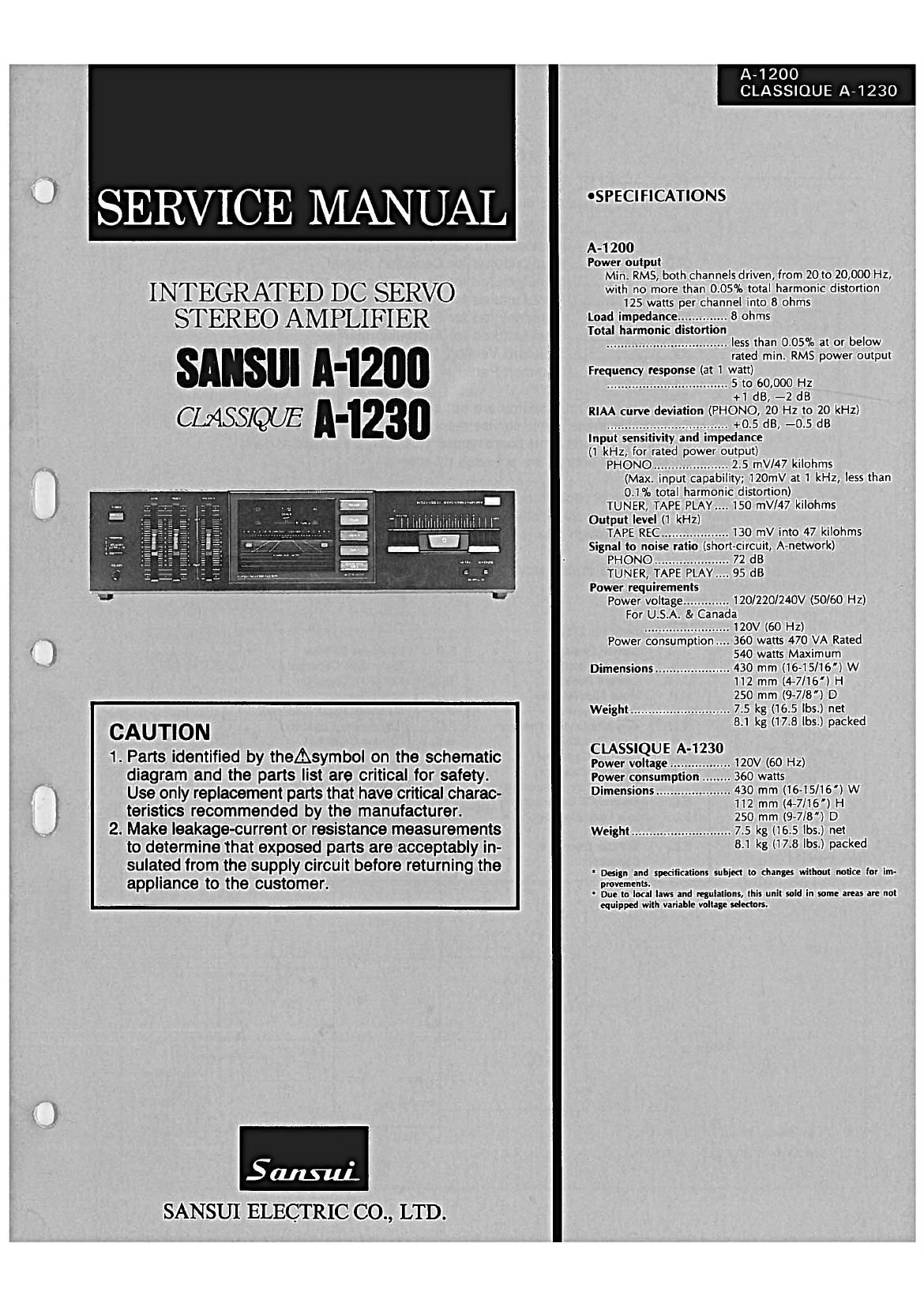
Sansui A 1200 Service Manual

This is the 13 pages manual for Sansui A 1200 Service Manual.
Read or download the pdf for free. If you want to contribute, please mail your pdfs to info@audioservicemanuals.com.

Page: 1 / 13
left right
Sansui A 1200 Service Manual

Extracted text from Sansui A 1200 Service Manual (Ocr-read)


Page 1

SERVICE MANUAL

INTEGRATED DC SERVO
STEREO AMPLIFIER

SANSUI ll-1200
MSW 0-1230

CAUTION

1. Parts identified by theAsymbol on the schematic
diagram and the parts list are critical for safety.
Use only replacement parts that have critical charac-
teristics recommended by the manufacturer.

2. Make leakage-current or resistance measurements
to determine that exposed parts are acceptably in-
sulated from the supply circuit before returning the
appliance to the customer.

SANSUI ELECTRIC CO., LTD.

A-1200
CLASSIQUE A-1230

OSPECIFICATIONS

A4200
Power output
Min. RMS, both channels driven, from 20 to 20,000 Hz,
with no more than 0.05% total harmonic distortion
125 watts per channel into 8 ohms
Load impedance .............. 8 ohms
Total harmonic distortion
.................................. less than 0.05% at or below
rated min. RMS power output
Frequency response (at 1 watt)
.................................. S to 60,000 Hz
+1 dB, -2 dB
RIAA curve deviation (PHONO, 20 Hz to 20 kHz)
.................................. +0.5 dB, -0.5 dB
Input sensitivity and impedance
(1 kHz, for rated power output)
PHONO ..................... 2.5 mV/47 kilohms
(Max. input capability; 120mV at 1 kHz, less than
0.1% total harmonic distortion)
TUNER, TAPE PLAY.... 150 mV/47 kilohms
Output level (1 kHz)

TAPE REC ................... 130 mV into 47 kilohms
Signal to noise ratio (short-circuit, A-network)
PHONO ..................... 72 dB

TUNER, TAPE PLAY.... 95 dB
Power requirements

Power voltage ............. 120/220/240V (50/60 Hz)
For U.S.A. 8: Canada
........................ 120V (60 HZ)

Power consumption 360 watts 470 VA Rated
, 540 watts Maximum
Dimensions ..................... 430 mm (16-15/16) W
112 mm (44/16) H
250 mm (9-7/8) D
Weight ............................ 7.5 kg (16.5 lbs.) net
8.1 kg (17.8 lbs.) packed

CLASSIQUE A-1 230

Power voltage................. 120V (60 Hz)
Power consumption .. .. 360 watts
Dimensions ..................... 430 mm (16-15/16) W

112 mm (4-7/16) H

250 mm (9-7/8) D
Weight ............................ 7.5 kg (16.5 lbs.) net

8.1 kg (17.8 lbs.) packed

Design and specifications subject to changa without notice for im-
provements.

Due to local laws and regulations, this unit said in some areas are not
equipped with variable voltage selectors.

Page 2

A4200
CLASSIOUE A-1230

CAUTION

1. The symbols, UL, CSA, SA, BS, UK, EU, AS and XX on the parts
list and the schematic diagram mean followings respectively.

UL ....................... Manufactured for U.S.A market.
(Underwriters Laboratories approved model.)

CSA .................... Manufactured for Canadian market.

SA_. ...................... Manufactured for South African market.

BS, UK ............... Manufactured for United Kingdom market.


XX ....................... Standard Version.

NON MARK ........ Common Parts.

EU .................... Manufactured for European market.
........ Manufactured for Australian market.

2. Some printed circuit boards are not supplied as the assembled.
To separate these in this service manual, the stock No's are not in-
dicated at the ends of the board names. However, the individual parts
on the circuit boards are provided by orders.

3. Since some of capacitors and resistors are omitted from parts lists
in this service manual, refer to the Common Parts List for capacitors
8. resistors, which was issued on February 1983.

4. Abbreviations in this service manual are as follows.

C.R.
S.Ft.
Ce.R.
M.R.
F.R.
N.I.R.
A.Ft.
C.C.
C.T.

E.C.
E.L.

E.B.

- OAbbreviations List

: Carbon Resistor

: Solid Resistor

: Cement Resistor

: Metal Film Resistor

: Fusing Resistor

: Non-lnflammable Resistor
: Array Resistor

: Ceramic Capacitor

: Ceramic Capacitor,

Temperature Compensation

: Electrolytic Capacitor
: Low Leak Electrolytic

Capacitor

: Bi-Polar Electrolytic

Capacitor

E.B.L.

Ta.C.
F.C.
M.P.
PC.
6.0.
A.C.
V.R.
S.V.R.
SW.
Chip R. :
Chip C. 2

: Low Leak Bi-Polar

Electrolytic Capacitor

: Tantalum Capacitor

: Film Capacitor

: Metalized Paper Capacitor
: Polystyrene Capacitor

2 Gimmic Capacitor

: Array Capacitor

: Variable Resistor

: Semi Variable Resistor

: Switch

Chip Resistor
Chip Capacitor