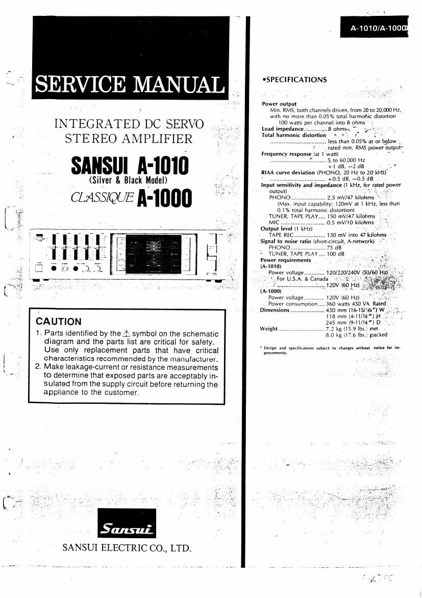
Sansui A 1000 Service Manual

This is the 3 pages manual for Sansui A 1000 Service Manual.
Read or download the pdf for free. If you want to contribute, please mail your pdfs to info@audioservicemanuals.com.

Page: 1 / 3
left right
Sansui A 1000 Service Manual

Extracted text from Sansui A 1000 Service Manual (Ocr-read)


Page 1

SERVICE MANUAL

INTEGRATED DC SERVO
STEREO AMPLIFIER

; snusur A-inio

(Silver & Black Model)

CLASS/QUE A4000

CAUHON

1. Parts identified by thei symbol on the schematic
diagram and the parts list are critical for safety.
Use only replacement parts that have critical
characteristics recommended by the manufacturer.

2. Make leakage-current or resistance measurements
to determine that exposed parts are acceptably in-
sulated from the supply circuit before returning the
appliance to the customer.

A-1010/A-100u

'SPECIFICATIONS

Power output
Min. RMS, both channels driven, from 20 to 20,000 HZ,
with no more than 005% total harmohic distortion

100 watts per channel into 8 ohms

Load impedance... ...,_._8 ohms. g

Total harmonic distortion : '-

.. less than 0 05% at or below

rated l'l'lll'1 RMS power output~

Frequency response (at 1 watt)

........................ 3. i to 60,000 HZ
+1 dB, -2 dB - '.

RIAA curve deviation (PHONO, 20 Hz to 20 kHz)

.. +05dB, -05dB.

Input sensitivity and impedance (1 kHz for rated power
output) . -
PHONO ..................... 2 5 mV/47 kilohms ' V

(Max. input capability; 120mV at 1 kHz, less than
(11% total harmonic distortion) .
TUNER, TAPE PLAY 150 mV/47 kilohms

MlC ..................... .. 0.5 mm kilohms » '
Output level (1 kHz) -.
TAPE REC_ 130 mV into 47 kilohms '

Signal to noise ratio (short-circuit, A-network)
PHONO 75 dB


TUNER, .. 100 dB
Power requirements
(IX-1010)
Power voltage .120/220/240V (50/60 H11

ForUSUA &Cariada 1-..2.

(A-1000

Power voltage.
. Power consumption
Dimensions.............

.. 120V (60 HZ) .
360 watts 450 VA Rated.
.. 430 mm (16-15116') W
118 mm (4-11/16') H
245 mm (9-ll/l6') D
Weight ........................... 7.2 kg (15 9 lbs}: net
8.0 kg (17.6 lbs.) packed


' Design and specifications subiect to changes wi|hoirt notice inr Im-
pmvamenis. ,

Page 2

3. OTHER PARTS

3-1. Front View

Dispiav Siege

(9;)

Paris List

a : .
-Tention Wire

A-1o1olA-1ooo ;

Parts No. Stock No. Description Parts No. Stock No. Description
1 47373500 From Panel (A4010 Silver Modell 10 07932500 Knob, BALANCE, MIC LEVEL
47373600 From Panel (A4010 Black Model) (A4010 Silver Model)
47373700 Front Panel (A4000) 47085900 Knob, BALANCE, MIC LEVEL
2 47367400 Knob, graphic E0. 80Hz, 280Hz, (A4010 Black Model, A4000)
5 1kHz, 3.5kHz, 12kHz 11 46862900 20k9x2 and 250k!) V,Fl.,
(A4010 Silver Model) BALANCE, MlC LEVEL
47367500 Knob, graphic E0. 80Hz, 280Hz, 12 46365100 Jack, MIC
1kHz, 3.5kHz, 12kHz 13 47005600 Knob, SPEAKERS
(A4010 Black Model, A-10001 (A4010 Silver Model)
3 46862800 Slide V.R., graphic E0. SOHZ, 07917300 Knob, SPEAKERS
ZBOHZ, 1kHz, 3.5kHz, i21

4 07952400 Bonner 14 46863000 Push SW., SPEAKERS
5 47213000 Knob, VOLUME 15 46862700 Jack, PHONES
(A4010 Silver Model) 16 07971210 Knob, POWER
47194200 Knob, VOLUME (A4010 Silver Model)
(A4010 Black Model, A4000) 07911210 Knob, POWER
6 46395300 150k9x2 V.R., VOLUME (A4010 Black Model, A40001
7 07917200 Knob, LOUDNESS A 17 46546900 Push SW,, POWER
(A4010 Silver Model)
07917300 Knob, LOUDNESS
(A4010 Black Model,A-10001
8 46360900 Push SW., LOUDNESS
9 46862300 PEAK POWER METER Ass'y

A-1010/A-1000

Parts List <1'op View>

Parts No. Stock No. Description Pans No. Stock No. Description
1 07917700 AC Cord Cover 6 22301510 GND Terminal
A 2 38005700 Power Supply Cord 7 46862600 2P lNPUT Terminal, PHONO
(A4010 XX, UL, A4000) 8 46371500 4P Terminal, TUNER, TAPE-l REC
A 46407700 Power Supply Cord (A4010 CSA) 9 46363900 6P Termlnal, TAPE-1 PLAY/DA,
A 3 15014501 Power Transformer (A4010 XX) TAPEAZ
A 15014502 Power Transformer 10 47448900 SidePanel Ass'y R
(A4010 UL, A4000] 11 07947200 Join! Shall
A 15014503 Power Transformer (A4010 CSAl 12 47448800 _ Side Panel Assy L
A 4 46863600 AC OUTLET '
5 46364100 8P Push Terminal, SPEAKERS \

3-3. Display Stage

005

£17275

Parts List

Pans No. Srock No. Description Pans No. Stock No. Description
1 47369600 Display Cover 7 46395900 Push SW, PHONO, TUNER, TAPE
2 47009510 Display Panel 8 07925510 Knob, PHONO
(A4010 Silver Model) 9 07925610 Knob, TUNER
07954410 Display Panel 10 07925710 Knob, TAPE-1
(A4010 Black Model, A4000) 11 47071410 Cushion
3 46365400 Push SW , TAPE-2, EOUALlZER, 12 47011500 Display Holder
POWER RANGE (A-1010 Silver Modell
4 07925810 Knob, TAPE-2 07947900 Display Holder
5 47369900 Knob, EOUALlZER (A-1010 Black Model, A4000)
6 47370000 Knob, POWER RANGE

4. BIAS CURRENT ADJUSTMENT (See Top View left)

Nola: 1. Room Temperature 18°C-28°C 3. Before rurning ON POWER switch, set kVR1 on
2. For this adjustmenr, removal of radiaior is required, F-4416 little before center.
so loosen rhree screws (5) 4. For adjusrmenr, run rhe unit for more than 5 minutes
after rhe power is swirched on.

SU BlECT MEASURE OUTPUT ADIUST ADJUST FOR REMARKS
LCH Connect DC V011 "19181 kVR1 (L-CH) DC SmVilmV This bias current adjustment COU-
beiween BIAS Terminals (F4416) vens current value into vltage 13!
(chh), on 64416 ohms law.
Absolutely, install the rad iaror alter
R-CH Connect DC volt meter kVRi (RCH) DC SmVMmV (his adiusrmenr.
between BIAS Terminals (E4416)
(R-chl, on F4416