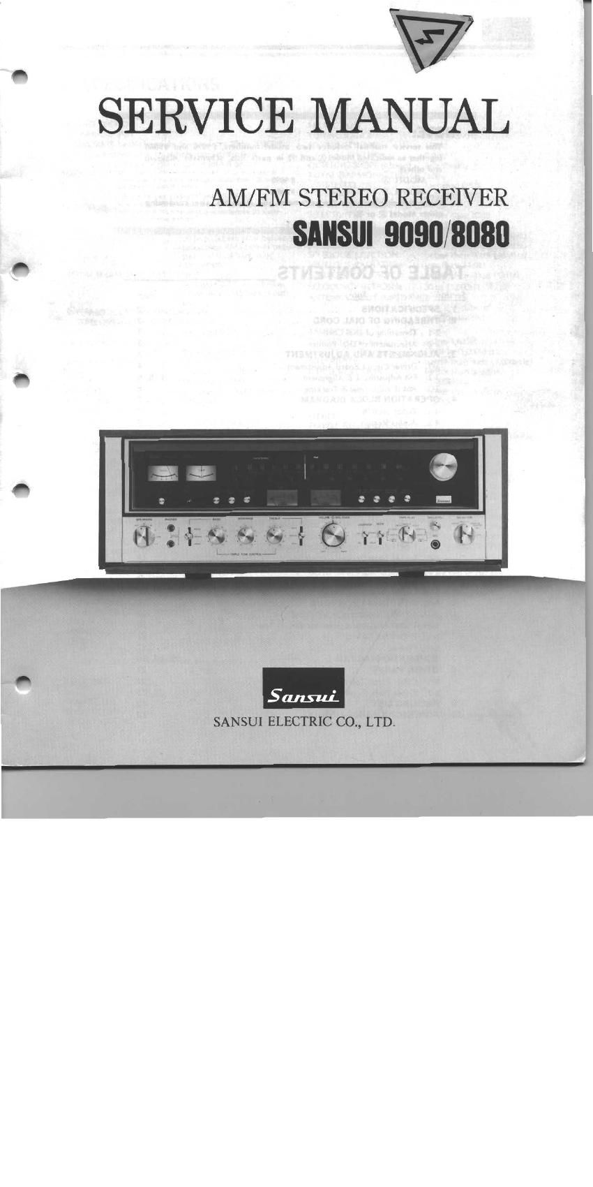
Sansui 9090 8080 Service Manual

This is the 30 pages manual for Sansui 9090 8080 Service Manual.
Read or download the pdf for free. If you want to contribute, please mail your pdfs to info@audioservicemanuals.com.

Page: 1 / 30
left right
Sansui 9090 8080 Service Manual

Extracted text from Sansui 9090 8080 Service Manual (Ocr-read)


Page 2

||I|I|Illl|llll|IIIIIIIIIIIIIIIIIIIIIIIIIIIIIIIIIIIIIIIIIIlllIIIIIIIIIllIlIIIllllllllllllllllilllllllllllIIIIIIIIIIIIIIIIIIIIIIII|llllllilllllllllllIIIllllIllllllllllllllllllllllllilllllllllllll
NOTE:

This service manual includes two model numbers, #9090 and #8080
together as indicated Model®and ® in parts lists, schematic diagram
and others.

MODEL ® .................... S 9090

MODEL ® .................... I? 8080
When ordering parts, use the parts name and stock No. after confirming
either Model ® or (E.

IIIIIllIllIlIIIIIIlIIIIIIIIIIIIIIIIIIIIIIIIIIIIIIIIIIllIlIlIIlIIIIIIIIIIIIIlIIIIIIIIlllIIIlIlIIllIIIIII|llllllIIIIIIIIIIIIIIIllllllllllIIIIIlllllllllllIlll|llllllllllllllllllIIIIIIIIIIIIIIIIIIll

TABLE OF CONTENTS

Section Lle Page
1. SPECIFICATIONS ................................................

2. THREADING 0F DIAL CORD ..............................

2-1. Threading of Dial Cord ..................................

2-2. Attachment of Dial Pointer ..........................

3. ALIGNMENTS AND ADJUSTMENT ....................

3-1. Driver Circuit Board Adjustment ......

3-2. FM Adjustment & Alignment ..........

3-3. AM IF Adjustmet 8x Tracking ..........................

4. OPERATION BLOCK DIAGRAM ........................

4-1. Tuner Section

4-2. Audio Section .....................................

5. TROUBLE SHOOTING CHART ...

5-1. Audio Section ................................................

5-2. Tuner Section ................................................


3
wmmuuumanawwwwn

6. PARTS LOCATION AND PARTS LIST ................... . 10
6-1. F2546 Power Supply Circuit Board ............................ 10
6-2. F-2547 Protector Circuit Board ................................ 1 1
6-3. F-2543 Tone Control Circuit Board ,. 11
6-4. F-2436 Driver Circuit Board .................................... 12
6-5. F~2545 Filter 8: Muting Circuit Board .......................... 12
6-6. F-2541 Equalizer Circuit Board ..................... . . 13
6-7. F-2431 Power Supply Circuit Board ............................ 13
6-8. F-2544 Tone Control Circuit Board ............................ 14
6-9. F-2542 Accessory Switch Circuit Board ........... .... 14
6-10. F<2549 FM, AM Tuner Circuit Board ........................ 15, 16
6-11. F-2550 Multi-Path Circuit Board ................................ 16
6-12, F-1470 Lamp Circuit Board . ........................ H 16
643, F-2597 Connector Circuit Board ................................ 16
6-14. F2548 Protector Connector Circuit Board ...................... 16
6-15. F-15'l9 FM PaCk ................................... . 17
6-16. Figures ............................................. 17

7. SCHEMATIC DIAGRAM .................................. 18, 19. 20
8. OTHER PARTS ..........
8-1. Other Parts (Top Side) ..

8-2. Other Parts (Front Side) .. ..

9. PACKING LIST ..............
10. ACCESSORY PARTS LIST . ........