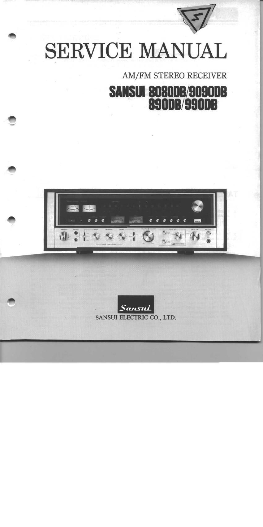
Sansui 890 DB 990 DB Service Manual

This is the 30 pages manual for Sansui 890 DB 990 DB Service Manual.
Read or download the pdf for free. If you want to contribute, please mail your pdfs to info@audioservicemanuals.com.

Page: 1 / 30
left right
Sansui 890 DB 990 DB Service Manual

Extracted text from Sansui 890 DB 990 DB Service Manual (Ocr-read)


Page 2

_ 8080DB/9090DB
llILVllL' 890DB/SQODB

This service manual is designed for service engineers to repair, adjust,

maintain and order the replacement parts of the 8080DB/909ODB, 89ODB/
99ODB correctly.

When ordering the parts, use the stock number and parts name speci-
fically referring to the Parts Location and Parts Lists.

For general usage and maintenance of the unit, please refer to the
Operating Instructions attached with the unit.

TABLE OF CONTENTS

Section E % Secsion ELL) [fl
1. SPECIFICATIONS .......... 2 543. F»2683 Connector Circnit Board ('8) ........ 14
2. BLOCK DIAGRAM .......... 3 5-14. F-2692 Connector Circuit Board .......... 14

2- 1. Audio Section . 3 5-15. F-2695 LED Assy Circuit Board ............ 14
2- 2. Tuner Section .4 , 3 5-16, F-Z654 Push Switch Circuit Board . 15
2- 3. Dolby Mode Section ........... 5 5-17. F-2655 Dolby NR Circuit Board ............ 15
3t OPERATION OF DOLBY FM SYSTEM. . 6 5-18. E-2623 Filter Circuit Board ................ 16
4. ADJUSTMENTS ........................... . 6 5-19. F-2693 Push Switch Circuit Board .......... 16
4- I. Dolby Circuit Adjustment 7 5-20. F-2694 Dolby Volume Circuit Board ...... 16
4- 2. Adjustment of Audio Section 8 5-21. F-2690 DIN Terminal Circuit Board .
4- 3. Adjustment of Tuner Section .. .. 9 5-22. Figures... ... . .
5. PARTS LOCATION AND PARTS LIST .. r 0 6. OTHER PARTS
5- l. F-2549 AM, FM Tuner CirCuit Board ...... 10 6- 1, Top Side tttttttttttttttt
5- 2t F2627 Illumination Circuit Board ........ 10 6- 2 Bottom Side
5- 3. F-1519 Front-end Pack .......... . 11 6- 3. Exploded View ..
5- 4. F-2653 Equalizer Circuit Board . 11 7. SCHEMATIC DIAGRAM ......
5- 5. F-2624 Driver Circuit Board .. 12 7- 1. Tuner Section
5- 6, F-2544 Tone Control Circuit Board ........ 12 (BOBODB/EXJBOBD, 89008/99003) ............ 19
5- 7. F-26l7 Mic AMP. Circuit Board ............ 13 7- 2. Audio Section (8080DB/890DB) ............ 20
5- 8. F-2619 Power Supply Circuit Board of 7- 3. Audio Section (909008/990DB) . . 21
RF Section ....... ._ t. 8. THREADING OF DIAL CORD . 22
5- 9. F-2657 Power Relay Circmt Board 8- It Threading of Dial Cord ., . 22
540. F-2656 Power Supply Circuit Board 14 8- 2. Attachment of Dial Pointer .............. 22
5-11. F-2684 Connector Circuit Board (C). . H 14 9. PACKING LIST ............... . back cover
5-12. F-2682 Connector Circuit Board (A). . ., . 14 10. ACCESSORY PARTS LIST .. . . back cover