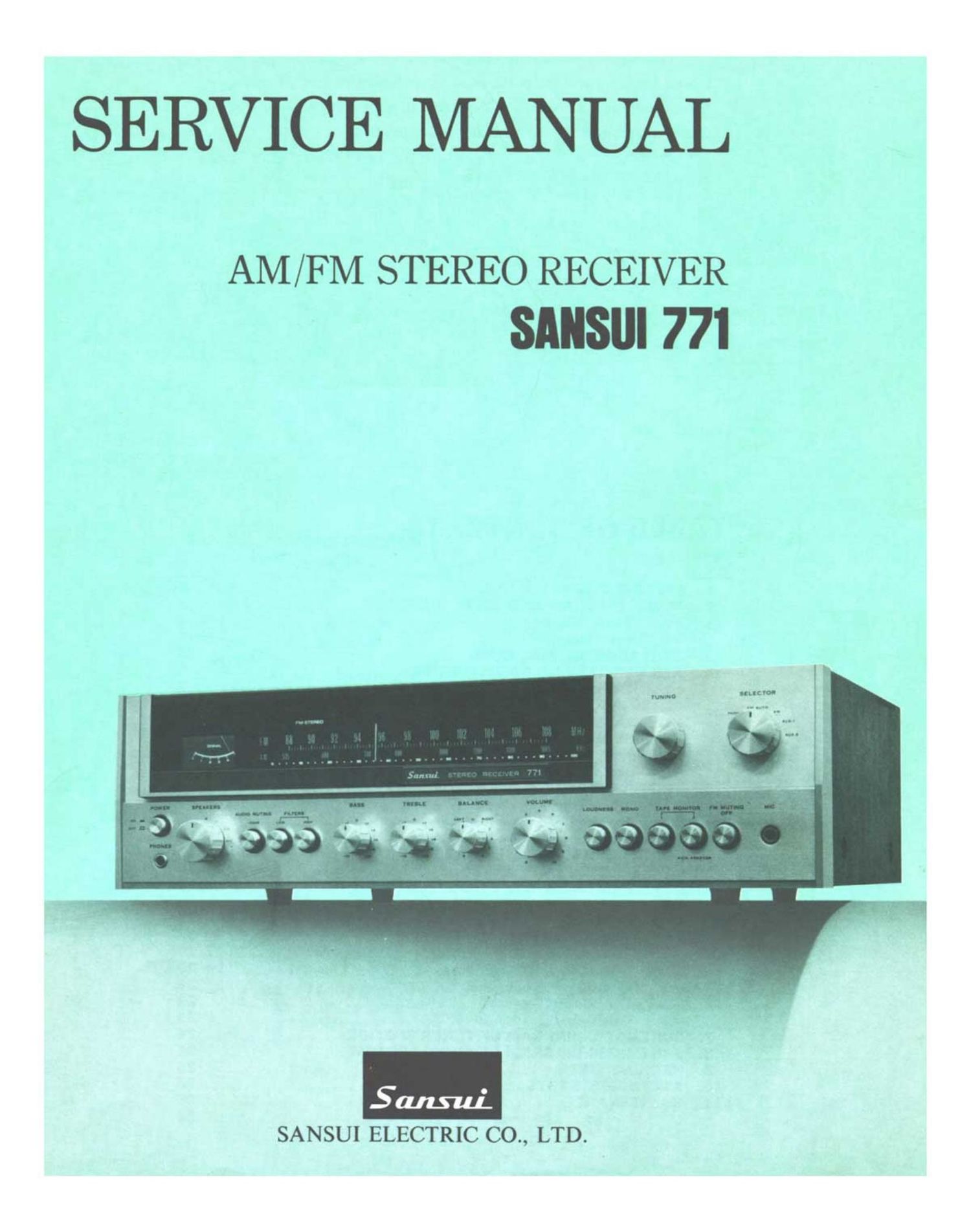
Sansui 771 Service Manual

This is the 31 pages manual for Sansui 771 Service Manual.
Read or download the pdf for free. If you want to contribute, please mail your pdfs to info@audioservicemanuals.com.

Page: 1 / 31
left right
Sansui 771 Service Manual

Extracted text from Sansui 771 Service Manual (Ocr-read)


Page 1

SERVICE MANUAL

AM /FM STEREO RECEIVER
SANSUI 7 71

SANSUI ELECTRIC CO., LTD.

Page 2

This service manual is designed for service engineers to repair,

adjust, maintain and order the replacement parts of the 771 correctly.
When ordering the parts, use the stock number and parts name speci-
fically referring to the Parts Locations 8: Parts List.

For general usage and maintenance of the unit, please refer to the
Operating Instructions attached with the unit.

TABLE OF CONTENTS

Section M 8183
1. SPECIFICATIONS ................................................ 2
2. BLOCK DIAGRAM AND LEVEL DIAGRAM ...................... 3

2-1. Block Diagram .......................................... 3, 4

2-2. Level Diagram ............................................ 4

3. THREADING OF DIAL CORD .................................... 5
4. ALIGNMENTS AND ADJUSTMENTS ............................ 6
4-1. Driver Circuit Board Adjustment ............................ 6
4-2. FM IF Alignment ............................................ 7
4-3. FM Dial Calibration and RF Alignment .................... 7, 8
4-4. FM Signal Meter, Mono Distortion and Muting Adjustment . . . . 8

4- -5. MPX Alignment ............................................ 9

4- 6. AM IF, Dial Calibration, RF and Signal Meter Alignment. . 9, 10

5. TROUBLESHOOTING CHART .................................. 11
S- 1. Troubleshooting on Power Supply Section .................. 11

5-2. Troubleshooting on'Audio Section .......................... 11

5-3. Troubleshooting on Tuner Section ...................... 11. 12

6. PARTS LOCATIONS AND PARTS LIST ........................ 13
6-1. F-I479D Tuner Circuit Board ........................ 13, 14, 15

6-2. F-1SO4 Mic & Tone Control Circuit Board .................... 15

6-3. F-1SO3 Equalizer Circuit Board .............................. 16
6-4. F4505 Filter Circuit Board .................................. 17
6-5. F-1490 De-emphasis Circuit Board .......................... 17

6-6. F-1499A Driver Circuit Board .......................... 17, 18

6-7. F-1500C Power Circuit Board .......................... 19. 20
6-8. Other Parts (Front Side) ................................ 21, 22

6- 9. Other Parts (Top Side) .................................... 23

6- 10. Other Parts (Bottom Side) .................................. 23

7. SCHEMATIC DIAGRAM OF TUNER SECTION .................. 24
8. SCHEMATIC DIAGRAM OF AUDIO SECTION .................. 25
9. PACKING LIST ................................................ 26
10. ACCESSORY PARTS LIST ...................................... 26
11. MAINTENANCE ................................................ 26

11-1. Voltage Adjustment .............. . ....................... 26

Page 30

9. PACKING LIST

Part: No. Stock No.

Description

1 9017340
2 9027770
3 9007540

Inner Packing (upper)
Stylofoam Packing
Carton Case

10. ACCESSORY
PARTS LIST

Stock No. Description

9406020 Polishing Cloth

0433640 5A Quick Acting Fuse
9207920 Operating Instructions
9227920 Operating Instruction Sheet

11. MAINTENANCE

11-1. Voltage Adjustment

The Voltage Selector on the rear panel enables you to
operate at correct voltage in any areas. The voltage has
been preadjusted at the factory, but can be easily
changed as follows, according to the line voltage using
in your area.

1) Remove the two screwse securing the name plate on
the unit's rear panel, then remove the name plate.

2) Unplug the Voltage Selector plug once, and reset it
so that the arrow mark on it faces the correct voltage
indication. Also change the power fuse when the
power supply voltage has change. For 100/117 volt
operation, use a S-ampere glass-tubed fuse. For 220/
240 volt operation, use a 3-ampere one.

Note: The Voltage Selector can be used to eliminate
the trouble caused by the considerable voltage
fluctuation. In this case, it should be set to the
peak voltage.

240V

240V ii7V