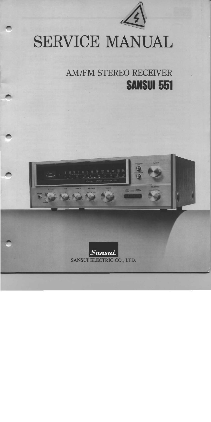
Sansui 551 Service Manual

This is the 24 pages manual for Sansui 551 Service Manual.
Read or download the pdf for free. If you want to contribute, please mail your pdfs to info@audioservicemanuals.com.

Page: 1 / 24
left right
Sansui 551 Service Manual

Extracted text from Sansui 551 Service Manual (Ocr-read)


Page 2

This service manual is designed for service engineers to repair,
adjust, maintain and order the replacement parts of the 551 correctly.
When ordering the parts, use the stock number and parts name
Specifically referring to the Parts Locations & Parts List.

For general usage and maintenance of the unit, please refer to the
Operating Instructions attached with the unit.

TABLE OF CONTENTS

Section M Page
1. SPECIFICATIONS .............................................. 2
2. BLOCK DIAGRAM AND LEVEL DIAGRAM ...... 3, 4
3. THREADING 0F DIAL CORD ................... 4

3-1. Threading of Dial Cord . .. ................ 4
3-2. Attachment of Dial Pointer ..................... 4
4. ALIGNMENTS AND ADJUSTMENTS ................. 5
4-I. Driver Circuit Board Adjustment ................. ., .. 5
4-2. FM IF Alignment ...................................... 6
4-3, FM Dial Calibration, MONO Distortion and RF Alignment .. 5, 7
4-4. MPX Alignment ............................................ 7
4-5. AM IF, Dial Calibration, RF Alignment ........... . . .. 8
5. TROUBLESHOOTING CHART .................................. 9
5-1. Troubleshooting on Power Supply Section .................. 9


5-2. Troubleshooting on Audio Section ...............
53. Troubleshooting on Tuner Section ...............
6. PARTS LOCATIONS AND PARTS LIST 4.
6-1. F1506 Tuner Circuit Board ........................

6-2. F4509 Pre Main Amp & Power Circuit Board ............ 13, 14

6-3. Other Parts (Top Side) ......................
6-4. Other Parts (Bottom Side). .
6-5. Other Parts (Front Side) ..................................


7. SCHEMATIC DIAGRAM ........................................ 17

8. PACKING LIST .................

9. ACCESSORY PARTS LIST ................................... 1 1s

Page 6

4. ALIGNMENTS AND ADJUSTMENTS A

Abbreviation
Equipment Others
AM FM Generator Oscilloscope .......... Genescope Clockwise ............................. CW.
AM Standard Signal Generator .. r . .AM 556 Counterclockwise CCW
FM Standard Signal Generator ............ FM 556 Antenna ........................... A.NT
FM Stereo Generator ............... Stereo 50 Modulation .............................. MOD
Oscilloscope ........ .UScope
Audio Oscillator ................. Audio Osc
Distortion Meter ........................ Distt Meter
4-1 . Driver Circuit Board Adjustment (See Fig. 4-1)
Note: 1. Master Volume ................ Minimum
2, Make the SP terminals free (no load).
3. After adjustment, run the unit for more than 5 minutes, then check and readjust necessary.
4. Room temperature should be 18~28° (65~83°F) for bias current adjustment.
MEASURE l V
STEP SUBJECT EQUIPMENT I OUTPUT ADJUST ADIUST FOR ;' CONDITION
1 Bias current DC milliammeter l F- 01509 F1509 20:1mA l nSlep down meters range
chh VRO9 } accordingly
(Foig 4- 1) (Fig. 4-1)
2 Bias current DC milliammeter l F- 1509 F1509 20:1mA a Change leads polarity if
R'Ch F02 VR10 meter swings backward
(Fig 4-1) (Figs 4-1) l
Fig. 4-1
bias current bias current
volume(L»CH) votume(R~CH)
__ R71 VR09 VRlO R72 _ q
F02
milliam- + +
meterfl»)
F-1509
a