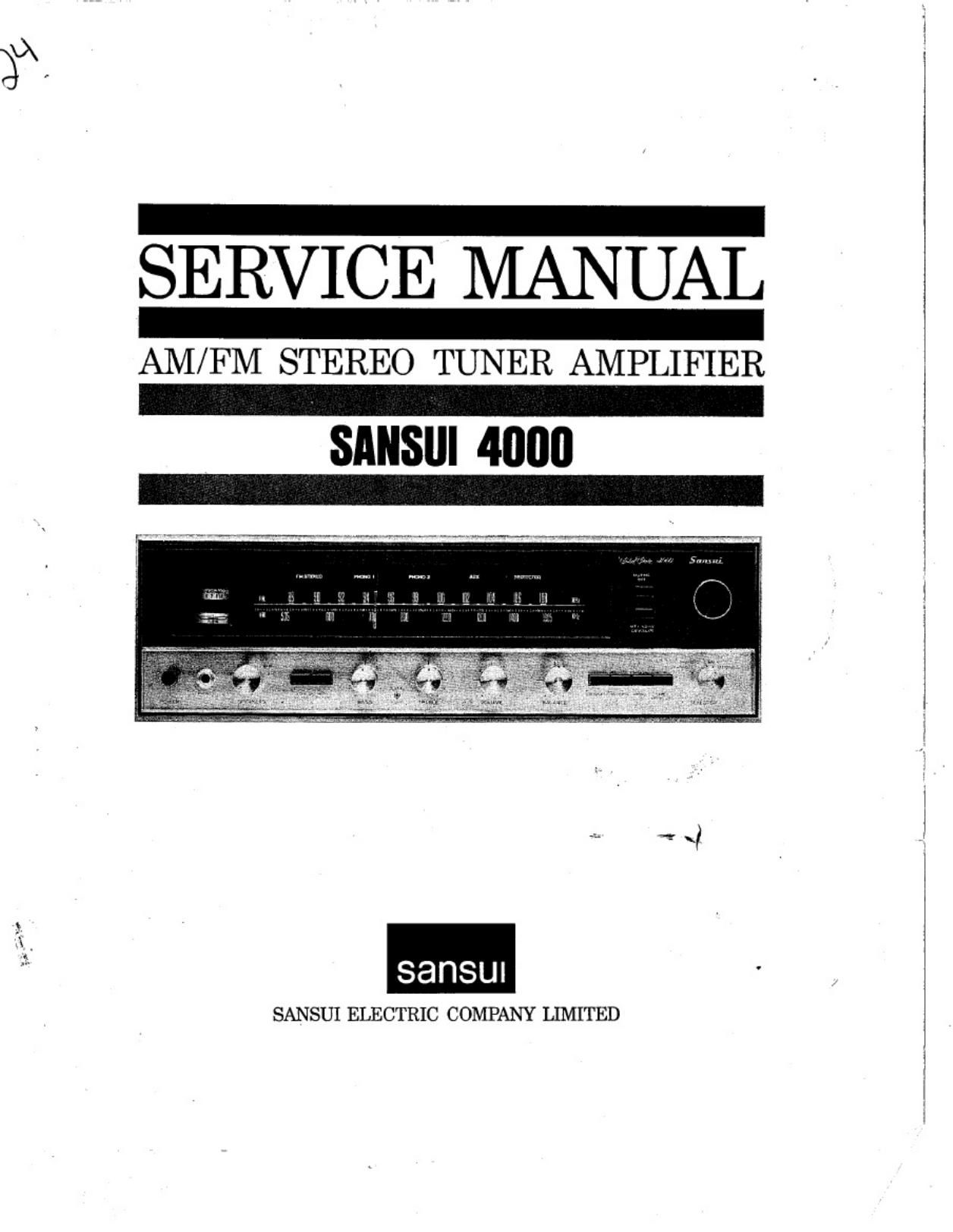
Sansui 4000 Service Manual

This is the 28 pages manual for Sansui 4000 Service Manual.
Read or download the pdf for free. If you want to contribute, please mail your pdfs to info@audioservicemanuals.com.

Page: 1 / 28
left right
Sansui 4000 Service Manual

Extracted text from Sansui 4000 Service Manual (Ocr-read)


Page 1

SERVICE MANUAL

AM/FM STEREO TUNER AMPLIFIER

SANSIII 4000

sansw

SANSUI ELECTRIC COMPANY LIMITED

Page 2

CONTENTS

GENERAL TROUBLESHOOTING CHART .................. 3, 4
DISASSEMBLY PROCEDURE .................................... 5
BLOCK DIAGRAM ................................................ 6
ALIGNMENT
-TEST POINT .................................................. 7
-FM ALIGNMENT PROCEDURE ............................ 8
-FM MULTIPLEX ALIGNMENT PROCEDURE .......... 9
-AM ALIGNMENT PROCEPURE .......................... 10
- ~CURRENT ADJUSTMENT ................................ 11
-OUTPUT ADJUSTMENT .................................. 12
-PROTECTOR ADJUSTMENT .............................. 12
PRINTED CIRCUIT SHEETS AND PARTS LIST
.................... 13, 14, 15, 16, 17, 18, 19, 20, 21, 22, 23, 24

OTHER PARTS CHART AND LIST ...................... 25, 26

Page 5

PROGRAM

SYMPTOM

l PROBABLE CAUSE

WHAT TO DO

FM reception
(oont'd)

B. A series of pops is
heard

C. Tuning noise between
stations

* Ignition noise caused by

an automobile engine

This results from the nature
of the FM reception. As
the station signal becomes
weak, the noise limiter effect
is decreased, and the amplifi -
cation of the limiter. in turn.
is enlarged. generating ' a
noise

* Install the antenna and its lead-in

wire in proper distance from the
road _or raise the antenna input as
described above

* Turn the MUTING switch on. It

reduces the sensitivity, and therefore
it should be used sparingly

FM-MPX
reception

A. Noise heard during
FM-MPX reception
while not heard during
FM mono reception

Weaker signal because the
service area of the FM-
MPX broadcast is only half
that of the FM mono broad-
cast

Install the antenna for maximum
antenna input

Switch on the high filter and/or turn
lhi? TREBLE control from midpoint,
e t

B. Clearness of channel
separation is decreased
during reception

Excess heat

* Circulation of air is important to the

amflifier. Be sure that air is flowing
un er the amplifier

C.7 The stereo indimtor
blinks on and off

Interference

The indicator is not at fault. Adjust
VRm

D. The stereo indicator
blinks on and off even
though stereo station
is not received

Interference

The indicator is not at fault. Adjust
VRm

Record playing
or tape playback

A. Hum or howling

B . Surface noise

Record player placed direct-
ly on speaker

Wire other than shielded
wire used

Loose terminal contact

Shielded wire too close to
line cord, fluorescent lamp
or other electrical appli-
ances

Nearby amateur radio sta-
tion or TV transmission
antenna

Place a cushion between the player
and the speaker box or place them
away from each other

The connecting shielded wire should
be as short as possible

Switch on the LOW FILTER and
adjust the BASS control from mid-
pomt, left

Consult the nearest Radio Regulatory
Bureau

i * Worn or old record

Worn needle

Needle dusty

" Improper needle pressure

Recondition the playback head of the
tape recorder or the needle the record
player

Ad'ust the TREBLE control from
midpoint. left

HIGH FILTER on

All stereo
programs

BALANCE control is not
at midpoint when equal

sound comes from left and
right channels

equal
channels.

point

It is important to adjust for
sound from both
It should not
always be set to the mid-

Set the MONO switch to MONO
and then set the BALANCE control
to a ition where equal sound
comes rom both channels