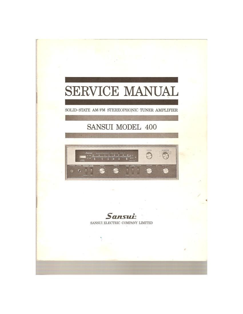
Sansui 400 Service Manual

This is the 32 pages manual for Sansui 400 Service Manual.
Read or download the pdf for free. If you want to contribute, please mail your pdfs to info@audioservicemanuals.com.

Page: 1 / 32
left right
Sansui 400 Service Manual

Extracted text from Sansui 400 Service Manual (Ocr-read)


Page 1

i SERVICE MANUAL
. -
5

SOLID-STATE AM/FM STEREOPHONIC TUNER AMPLIFIER

SAN SUI MODEL 400

I .
501mm
SANSUI ELECTRIC COMPANY LIMITED

I

Page 2

SANSUI

SOLID-STATE
am/fm-mulutiplex

STEREO TUNER AMPLIFIER

MODEL-400
HOW T0 USE THIS SERVICE MANUAL

1. Look up the type of trouble you are confronted with in either
the General Troubleshooting charts'provided in this manual from
pp 2-11V

2. By referring to the charts, isolate the trouble to a particular
unit or part. [See the column titled What To Do" in the General
Chart and. Check Point in the Troubleshooting Chart)

3. Locate the section of the chassis (Parts Layout P. 13y, in which
the part is located by using the co-ordinates IColurnn D) in 'the
Parts List pp. 25-29,

4. Using the eta-ordinates given in the Parts List (Column Cl,
pinpoint the position of the part in the Schematic Diagram of
Circuits, pp. 15-16.

NOTE: Much of the information contained in this manual has
been prepared for use by qualified service repairmen. Please read
your Warranty thoroughly before attempting any internal adjust-
ments on your own.

CONTENTS

GENERAL CHART
TROUBLESHOOTING CHART ,.
OVER ALL PROGRAM SOURCES.
AM RECEPTION ............
FM MPX STEREO RECEPTION
FOR USE WITH A RECORD PL
(MAGNETIC) OR A TAPE DECK .
OTHER PROGRAM SOURCES
RECORDING ON TAPE .....
GENERAL DISASSEMBLY PROCEDURE


BOTTOM PLATE/DIAL MECHANISM . 12
PARTS LAYOUT ..... . .................. 13
BLOCK DIAGRAM OF PRINTED CIRCUITS . l4
SCHEMATIC DIAGRAM 0F CIRCUITS 15, 16

SELECTOR SWITCH CHART
ALIGNMENT ..............
PRINTED-CIRCUIT SHEETS
PARTS LIST . '
COLOR CODE ._

17

18, 19, 20, 21

22, 23, 24

25, 26. 27, 28, 29
30

Page 4

GENERAL CHART

PROGRAM] SYMPTOM l PROBABLE muse WHAT To no

FM reception. B, Emission of a * Ignition noise caused by the " Install the antenna and its lead-in

(continued) scratching sound starting of an automobile engine wire a to proper distance from the
reed or raise the antenna input
as previously described.

C. Distortion or no ' Tuning drift results from the The built-in automatic fre uency con-
sound during the nature of FM trol prevents distortion tiring FM
reception reception. If the FM progrem should

out of tune due to mechanical
\ihrationor other factors, retuue it.
D. Tuning noise bet " This noise results from the naturc The unit is not at fault. Reduce
tween stations of FM reception. As the station the sound level before turning the
signal becomes weak the noise TUNING knob.
lirnter eflect is aTso decreased
The amplification of the limiter,
in turn, is enlarged and emits a
larger noise
FM-MPX A. Noise hoard during * Weaker signal because the service Install an antenna for maximum
stereo recep FM-MPX illstereo nrenlolh t1hfe {Mtg} Itzroadcast antenna input
tion reception w ie not is on y a t at o t e M mono _.
heard during FM broadcast Smtch on the NOISE FILTER
mm me on and/or turn the TREBLE control
P properly from midpoint to lett
B. Cleamess of channel Improper Ventilation. Make sure that air can flow above
separation is dec- Air circulation is important to the and below the unit
reused during the smpliiiers performance
reception
C. The stereo indicator * Interference. The indicator is Adjust V
goes on and off , not at fault.
D. The stores indicator Interference. The indicator is Adjust \Rm
goes on and off even not at fault.
though a stereo sta-
tion is not received 7 7 ,
Reoord or A. Hum or howling l * Record player placed directly on . Put a cushion between the player
tape playing the speaker box and the _speaker box or separate
'4 Use or wire other then shielded m mm?
wire ' The connecting card should he as
" Loose terminal Contact . 1° as posmblel l
- Shielded wire too close to the Red "3 55 °d"°ssP'°Py
line card. fluorescent lamp or
other electrical appliances
Nearby amateur radio station or Consult the nearest Radio Re-
TV transmission antenna gulatory Bureau
B. Surface noise Worn or old record Turn the TR'EBIrE control pro-
. Worn pickvup needle perly trot-n midpoint to left
. _.
. Needle covered with dust 5"h n 9 N015": FILTER
. .. . - _ .
Improper needle pressure 1 the pm" "9 mam
Over all The BALANCE control The BALANCE control should " 5 the control to the position
stereo is not at the midpoint not be always set at midpoint where equal sound comes from
program: when equal sound oorne both channels
from left and night. t Check for unequal program loud-
dlannels n55