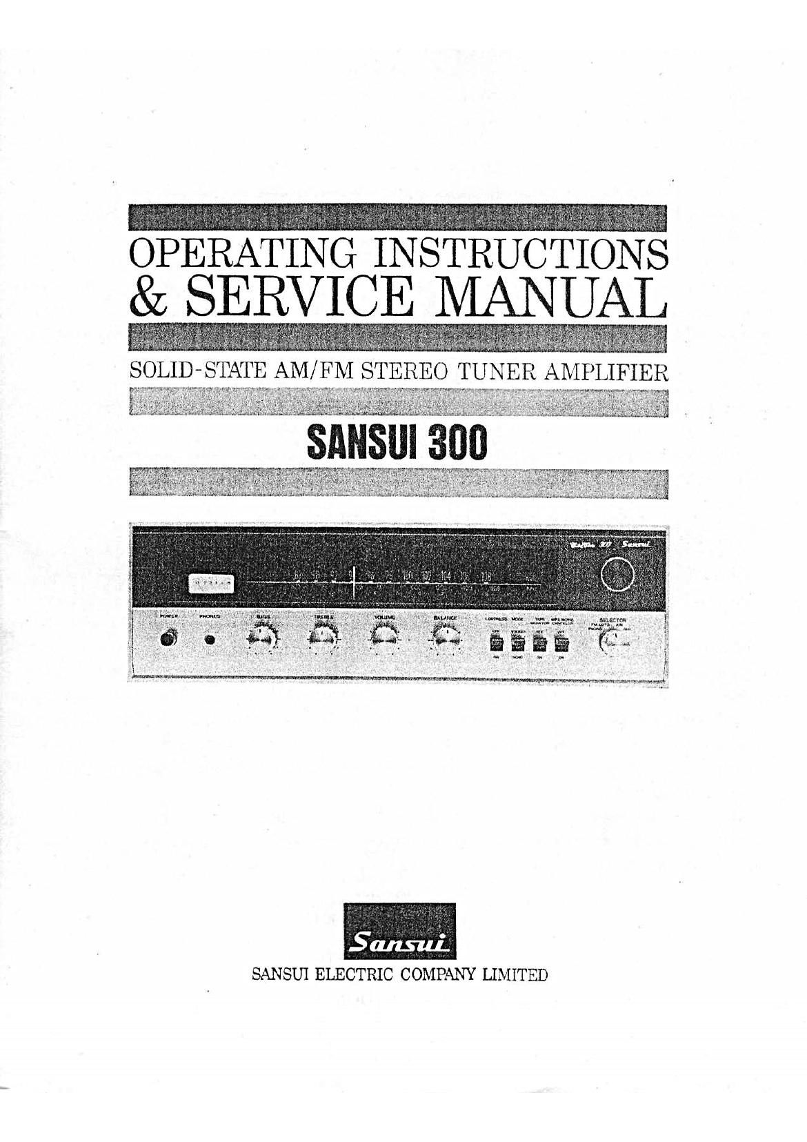
Sansui 300 Service Manual

This is the 34 pages manual for Sansui 300 Service Manual.
Read or download the pdf for free. If you want to contribute, please mail your pdfs to info@audioservicemanuals.com.

Page: 1 / 34
left right
Sansui 300 Service Manual

Extracted text from Sansui 300 Service Manual (Ocr-read)


Page 1

& SERVIC

SOLID- STATE AM/ FM STEREO TUNER AMPLIFIER

379'»

SANSUI ELECTRIC COMPANY LIMITED

Page 2

In selecting the Sansui 300 AM/FM Stereo Tuner Amplifier, you
have made a wise choice, one that will offer you years of quality
stereo enjoyment.
Like all Sansui products, the 300 combines the finest in internal
engineering, performance and design. It has been precision built,
tested and re~tested to perform flawlessly within the limits of its
specifications.
This manual has been prepared to help you keep the 300 in per-
fect operating conditions. It explains all of the 300s unique fea-
tures, installation and playing procedures, as well as some basic
maintenance requirements.

' Please read the contents of this manual carefully before operating
the receiver. You will then be better prepared to hear the 300
perform up to its full capabilities.

CONTENTS

M
SWITCHES AND CONTROLS ................................ 3 4

OPERATION ...................................................... 5, 6
-SPEAKER CONNECTION
-RECORD PLAYING

OPERATION ...................................................... 7, 8
-ANTENNA CONNECTION

-RADIO RECEPTION

OPERATION .................................................... 9, 10
-TAPE PLAYBACK
-TAPE RECORDING
MAINTENANCE .......................................... 11, 12, 13
SPECIFICATIONS ................................................ 14
TROUBLESHOOTING CHART ............................ 15, 16
DISASSEMBLE PROCEDURE/ DIAL MECHANISM ------------ 17
BLOCK DIAGRAM ................................................ 18
ALIGNMENT
-TEST POINT .................................................. 19
-FM ALIGNMENT PROCEDURE .......................... 20
-FM MULTIPLEX ALIGNMENT PROCEDURE .......... 21
--AM ALIGNMENT PROCEDURE .......................... 22
PRINTED CIRCUIT BOARDS AND PARTS LIST
.............................. 23, 24, 25, 26, 27, 28, 29

OTHER PARTS AND THEIR POSITION ON CHASSIS
.................................................. 29, 30

Page 17

SPECIFICATIONS

AUDIO SECTION
POWER OUTPUT
MUSIC POWER (IHF): 36W (at 4 ohms load)
32W (at 8 ohms load)
CONTINUOUS POWER (each channel):
Ié/IOW (at 4 ohms load)
H/IAW (at 8 ohms load)
TOTAL HARMONIC DISTORTION:
less than 1% at rated output
POWER BANDWIDTH (IHF):
30 to 25,000Hz (at 8 ohms load)
FREQUENCY RESPONSE (at normal listning level):
AUX OVER ALL: 25 to 30,000H21-2dB
CHANNEL SEPARATION: (at 1,000HZ rated Output)

PHONO: better than 40dB
AUX: better than 45dB
HUM ANO NOISE (IHF)
PHONO: better than 65dB
AUX: better than 70dB
INPUT SENSITIVITY (at 1,000Hz rated output):
PHONO: 3mV (50k ohms)
AUX' ISOmV (100k ohms)

TAPE MON (PIN): ISOmV (IOOk ohms)

TAPE RECORDER (DIN): IBOmV (IOOk ohms)
RECORDING OUTPUT

TAPE REC (PIN): I80rnV

TAPE RECORDER (DIN): 30mV
LOAD IMPEDANCE: 4 to 16 ohms
DAMPING FACTOR: 20 at 8 ohms load
EQAULIZER PHONO: RIAA, NF type
TONE CONTROLS

BASS. i IOCIB at 50H:

TREBLEZ iIOdB at I0,000Hz
LOUDNESS CONTROL: +1 IdB at 50Hz, +3dB

I0,000Hz (Volume Control at

-30dB)
SWITCHES
SELECTOR: PHONO, FM AUTO, AM, AUX
TAPE MONITOR: OFF, ON
MODE: STEREO, MONO

MPX NOISE CANCELER: OFF, ON
OTHER SPECIAL FEATURES
DIN Connector for Tape Recorder, Direct Tape Monitor
Head Phone iack,

\

TUNER SECTION
FM
TUNING RANGE: 88 to 108 MHz
SENSITIVITY (20dB quieting): 2.5;:V
(IHF): 311V

HARMONIC DISTORTION: less than I%
SIGNAL TO NOISE RATIO: better than 50dB
SELECTIVITY: better than 35dB at 98MHz
CAPTURE RATIO (IHF): 3d8
IMAGE FREQUENCY REJECTION:

better than 45dB at 98MHz
IF REJECTION: better than 60dB at 98MHz
SPURIOUS RESPONSE REJECTION:

better than 60dB at 98MHz
SPURIOUS RADIATION: less than 34dB
ANTENNA INPUT IMPEDANCE:

300 ohms balanced, 75 ohms

unbalanced
FM STEREO SEPARATION:

better than 30dB at 400Hz

AM
TUNING RANGE: 535 to I605kHz
SENSITIVITY: SIdB/m at I,OOOKHz

(bar antenna)
IMAGE FREQUENCY REJECTION:
better than 55dB at I,OOOkHz
IF REJECTION: better than 45c!
SELECTIVITY: better than 20dB
OTHER SPECIAL FEATURES:
FM Linear Scale Dioi, Signal Strength Meter, Fly-wheel
Tuning, AM Ferrite Bar Antenna, MPX Noise Canceler.
TRANSISTORS AND DIODES
Transistors: 36, FET: I, Varistors: 2, Thermistor: I
Diodes: I8, Zener Diode: I
POWER REQUIREMENTS
POWER VOLTAGE: 100, no, 117, 127, 220, 230,
240, 250V 50,"60Hz
POWER CONSUMPTION: ISVA (Zero Signal),
IOOVA (Max Signal)

DIMENSIONS I5-7/8"W 4-9/IéH
II-I/16D
WEIGHT 21 lbs.

" All rights reserve specifications subject to change without notice.

_14_

Page 18

TROUBLESHOOTING CHART

If the amplifier is otherwise operating satisfactorily
the more common causes of trouble may generally

be attributed to the following:

1. Incorrect connections or loose terminal contacts.
Check the speakers, record player, tape recorder,

antenna and line

2. Improper operation. Before operating any audio

cord.

structions.

3. Improper location of audio components. The

proper positioning of components, such as speakers

and turntable, is vital to stereo.
4. Defective audio components.

Following are some other common causes of mal-

component, he sure to read the manufacturers in-

function and what to do about them.

Poor noise limiter effect

PROGRAM SYMPTOM PROBABLE CAUSE WHAT TO DO

AM. FM or A. Constant or inter. * Discharge or oscillation * Attach a noise limiter to the

MPX reception mittent noise heard at caused by electrical appli- electrical appliance that causes the
certain times or in a ances, such as fluorescent noise. or attach it to the power
certain area. lamps, TV sets, D.C.. mo- source of the amplifier.

tors, rectifier and oscrllator * Install an outdoor antenna and
* Natural phenomena, such ground the ampliher to raise the
i as atmospherics, static, and signal-to-noise ratio.
thunderbolt. * Reverse the power cord plug-
* lnsuflicnent antenna input receptacle connections.
' gvuaiilstoorrfdhfohigilanicenfighi * If the noise occurs at a certain
; I the station g : frequency, attach a wave trap to
l i f f the ANT. input.
i * Wave inter erence rom
. l - , - * Place the set away from other clec-
l other electrical appliances trical appliances.
- B. Needle of the tuning l * Needle movement is not l * Tune the set for maximum signal
meter does not move necessarily related to thci strength.
sharply. sensitivity of the amplifier. 3
C. Zero point of the meter i * Regional difference in field l * The unit is not at fault.
moves greatly. intensity. ;

AM reception A. Noise heard at a i * Natural phenomenon. v * Install an antenna for maximum
particular time of day, l l antenna efficiency. See "ANTEN-
in a certain area or I 3 NA" in the Operating Instructions.

1 . l .
over part Of the dlal I l * In some cases. the norse can be
i l eliminated by grounding the ampli-
; her or reversing the power cord
; plug-receptacle connections.
8. High-frequency noise * Adjacent-channel interfer-l * Although such noise cannot be
ence or beat interferencel eliminated by the amplifier, it is
l advisable to turn the TREBLE
control from midpoint to left.
* TV set is too close to the * Place the TV set away from the
audio system audio system.
FM reception A. Noisy * *

or too low S/N ratio due
to insufficient antenna in-
put.

NOTE: FM reception is affected considerably by
the conditions of the transmitting stations: power .
and antenna efficiency. As a result, you may
receive one station quite well while having
difficulty receiving another station.

Adjust the antenna (supplied) for
maximum signal strength.

If this is not effective, use an out-
door antenna designed exclusively
for FM. \Nhen you use a TV
antenna for both TV and PM with
a divider, make sure TV reception
is not affected.

An excessively long antenna may
cause nmse.

_15._