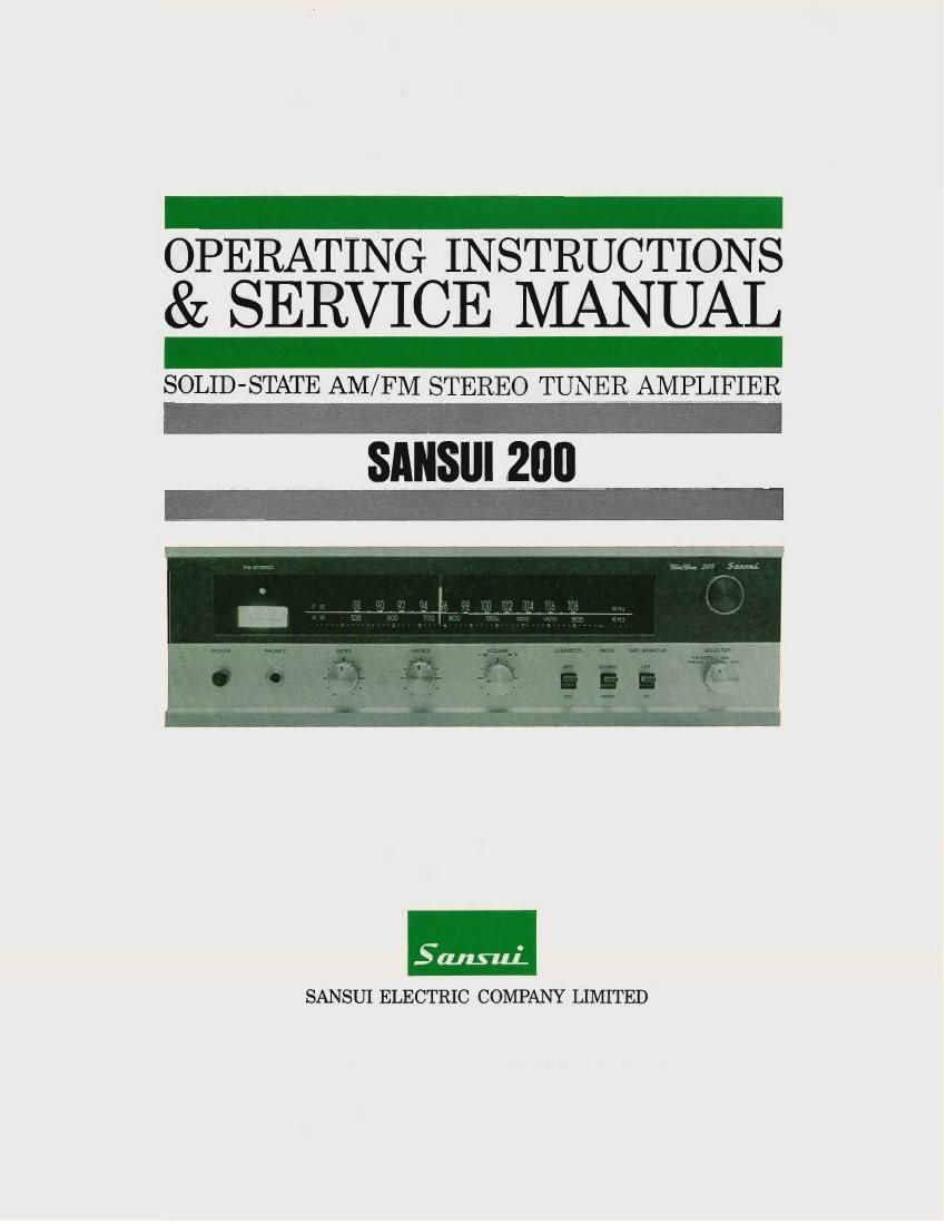
Sansui 200 Service Manual

This is the 31 pages manual for Sansui 200 Service Manual.
Read or download the pdf for free. If you want to contribute, please mail your pdfs to info@audioservicemanuals.com.

Page: 1 / 31
left right
Sansui 200 Service Manual

Extracted text from Sansui 200 Service Manual (Ocr-read)


Page 1

OPERATING INSTRUCTIONS
& SERVICE MANUAL

SOLID-STATE AM/ FM STEREO TUNER AMPLIFIER

SANSIII 200

SANSUI ELECTRIC COMPANY LIMITED

Page 2

In selecting the Sansui 200 AM/FM Multiplex Stereo Tuner Am-
plifier, you have made a wise choice, one that will offer you years
of quality stereo enjoyment.

Like all Sansui products, the 200 combines the finest in internal
engineering, performance and design. It has been precision built,
tested and re-tested to perform flawlessly within the limits of its
specifications

This manual has been prepared to help you keep the 200 in per-
fect operating conditions. It explains all of the 200s unique fea-
tures, installation and playing procedures, as well as some basic
maintenance requirements.

Please read the contents of this manual carefully before operating
the receiver. You will then be better prepared to hear the 200
perform up to its capabilities.

CONTENTS

SWITCHES AND CONTROLS .................................. 3, 4
OPERATION ...................................................... 5, 6
-SPEAKER CONNECTION
-RECORD PLAYING
OPERATION ...................................................... 7, 8
-ANTENNA CONNECTION
-RADIO RECEPTION
OPERATION .................................................... 9, 10
-TAPE PLAYBACK
-TAPE RECORDING

MAINTENANCE ............................................ 11, 12, 13
SPECIFICATIONS .................................................. 14
SCHEMATIC DIAGRAM ...................................... 15, 16
TROUBLESHOOTING CHART .............................. I7, 18
DISASSEMBLE PROCEDURE /DIAL MECHANISM ........ 19
ALIGNMENT
-TEST POINTS .................................................. 20
-FM TUNER ALIGNMENT PROCEDURE .................. 21
-FM MULTIPLEX ALIGNMENT PROCEDURE .......... 22
-AM TUNER ALIGNMENT PROCEDURE ................ 23
PRINTED CIRCUIT SHEETS AND PARTS LIST
.......................................... 24, 25, 26, 27, 28

OTHER PARTS AND THEIR POSITION ON CHASSIS
...................................................... 29, 30

Page 4

SWITCHES AND CONTROLS

FM Stereo Indicator
This indicator automatically lights up when a
stereo program is received. During mono recep-
tion, it remains unlit.

Tuning Meter
This meter aids in pinpointing a station. The
station, on either FM or AM band, is correctly
tuned when the pointer has swung as far to the
right as it will go.

Power Switch <-
Push to turn the power on; push again to turn
the power off.

Headphones Jack <-4
To monitor a tape or to enjoy late-night listening
through a headset without disturbing others, plug

into this jack. Your speakers are turned off when

the headphones are plugged into. This jack will
accept any standard phono plug, but dynamic
stereo headphones (Sansui 55-2) are recommend-

ed for use.

Bass Control
This control is used to boost or cut low-end
response according to personal taste, speaker
response and listening conditions. With the con-
trol in the mid-position the bass tones will sound
exactly as recorded or broadcast. To emphasize
the bass, turn it clockwise. To decrease the in-
tensity of the bass tones, turn it counterclockwise.

Treble Control

Use in the same manner as the BASS control to
boost or reduce high-end frequency response.

Volume Control
This control consists of two concentric knobs.
The outer black ring affects the right channel,
and the inner silver knob, the left. The pair can
be used simultaneously or independently, as re-
quired.

Normally, the entire control rotates as one unit.
If you wish to increase the overall sound level of
both channels, simply turn the VOLUME control
clockwise.

If you want to balance the sound levels in the
right and left channels in stereo mode, hold one
of the knobs in place while adjusting the other.

Mode Switch

STEREO: The MODE switch in the STEREO
position connects the left input to the left speak-
er and the right input to the right speaker. To
listen to an FM multiplex stereo program, stereo
record or stereo tape, set this switch to STEREO.
MONO: The MODE switch in the MONO posi-
tion connects either right or left, or both inputs,
to the speakers of both channels.

5 Loudness Switch

This switch provides the correct amount of bass
and treble boost required to compensate for an
apparent loss of bass and treble at low listening
levels.

Tuning Knob
Turn this knob to select the desired FM or AM
stations.

Dial Scales

The upper scale indicates FM and the lower AM.
To select a desired station, turn the Tuning knob
at the right of the dial.

Selector Switch

Select the desired program source with this
switch.

PHONO-Turn to this position to hear records
being played on a phonograph connected to the
PHONO input jacks on the rear.

FM AUTO-To hear FM broadcasts. In this
position, the switch automatically selects the cor-
rect mode.

AM-To hear AM broadcasts.

AUX-To hear a component connected to the
AUX inputs on the rear.

Tape Monitor Switch

This switch enables you to compare a recorded
tape with the original program. When it is turned
on, the tape being recorded is heard from the
speakers. Monitoring is possible with 3-head tape
recorders only. When you play back through the
amplifier, it should be in the ON position as well.
In all other cases, make sure it is in the OFF
position.

Page 26

PRINTED CIRCUIT SHEETS AND PARTS LIST

EQUALIZER CIRCUIT

AUDIO CIRCUIT

X Y 2
Root 110 110% MW Carbon Resistor 315
R602 110 110% MW Carbon Resistor 3A
Rec: 5610 110% MW Carbon Resistor 313
R604 56k!) 110% MW Carbon Resistor 3A
R605 3900 110% MW Carbon Resistor 213,33
R605 3900 110% MW Carbon Resistor 2A,3A
R607 2210 110% MW Carbon Resistor 23,33
R600 2210 110% MW Carbon Resistor 2A,3A
R509 220k0 110% MW Carbon Resistor 1 313
R610 22010 110% MW Carbon Resistor 3A,3B
R511 27010 110% MW Carbon Resistor 213,33
R512 270kfl 110% MW Carbon Resistor 2Ar3A
R613 4700 110% MW Carbon Resistor 25
Rsti 4700 110% MW Carbon Resistor 2A
R615 oak!) 110% MW Carbon Resistor 10,23
Rélé 6.8110 110% MW Carbon Resistor 1A.2A
R617 22R0 110% MW Carbon Resistor IB
Rein 221:0 110% MW Carbon Resistor 1A
Rm 220m 110% Mw Carbon Resistor 113
R020 220] 110% MW Carbon Resis'or IA
R521 2.2100 110% MW Carbon Resisior TB
R522 221(5) 110% MW Carbon Resistor IA
R523 22051 110% MW Carbon Resistor 2A
Rm 4700 110% MW Carbon Resistor 15
Cool IpF 113% 10 wv Tantalum Capacitor 311
C502 10F 33% 10 WV Tantalum capacitor 3A
Cm ISOpF 110% 50 WV Ceramic Capacitor 31;
C604 I50pF 110% 50 WV Ceramic Capacitor 3A
C605 47% :103% 6.3 WV EIecrqlvhc (2133231,) 25
Coca 47oF :'°g% 6,3 WV E"°'V"° ngpgg'g) 2
C607 10/11: :108% 25 WV Electrolytic 12:51:21,123 25
Coos my" :0396 25 WV Electrolytic C($$::I0(321) 2A
Com 150p1 110% 50 WV Ceramic Capacitor 20
C610 150pF 110% 50 WV Ceramic Capacitor 2A
C61] 100/: :103% 6,3 WV Electrolytic C(?;::1100v) 23
C612 100,21 :°3% 6.3 wv "WWW $353337) 2A
C613 U: :103% 50 WV Electrolytic $333005 25
C614 1% :108% 50 WV E1ectro1yric C(asggttoor) 2A
C615 470; :'°g% 25 WV WW" 2333333 3A,
C617 0.003rtr 110% 50 WV Mylar Capacitor 13
Core 000301 110% 50 wv Mylar Capacitor TA
C619 0.012pF 110% 50 WV Mylar Capacitor 13
C620 0.0120F 110% 50 WV Mylar Capacitor 1A
TRbOl 25c071 E, F (0305471-1,-2) 313
TRsoz 25Ca71 E, F (030547-11) 3A
TRsoa 25ca70 r (030551-11 2 B
TRém 25C870 F (030551-1) 2A
VRsai 5101a Separation Aaiustor (103018-1) 2A

X Y 2
Real 10120 110% MW Carbon Resistor 1C
R002 1010 110% MW Carbon Resistor 3C
R803 221(0. il0% MW Carbon Resistor IC
R504 2210 110% MW Carbon Resistor 3c
R805 100k0 110% MW Carbon Resistor 1Cr2C
R806 10010 110% MW Carbon Resistor 2C
R807 82!) 110% MW Carbon Resistor 1C
R900 1 820 110% MW Carbon Resistor 3C
R809 MR!) 110% Mw Carbon Resistor 1C
R810 2.210 110% MW Carbon Resistor 3C
R011 5.6kfl 110% MW Carbon Resistor 1C,2C
Rm 5.610 110% MW Carbon Resistor 2c
R613 1010 110% MW Carbon Resistor 1C,2C
R814 1010 110% MW Carbon Resistor 2C
R515 5.610 110% MW Carbon Resistor 1C
R015 5.610 110% MW Carbon Resistor 3C
R317 4700 110% MW Carbon Resistor 1C,2C
Raw 4700 110% MW Carbon Resistor 1 2C
R019 2200 110% MW Carbon Resistor 10
Rm 2200 110% MW Carbon Resistor 3D
R511 330 110% MW Carbon Resistor 20
R822 1 330 110% MW Carbon Resistor 20
R023 1.5k0 110% MW Carbon Resistor 1C12C
R824 I.5| R1325 1500 110% MW Carbon Resistor 1C
Rm 1500 110% MW Carbon Resistor 3D
R527 150 110% MW Carbon Resistor 1D
Rm 150 110% MW Carbon Resistor 30
R529 1500 110% MW Carbon Resistor 1C,2C
R830 1 1500 110% MW Carbon Resistor 2c
R031 220 110% MW Carbon Resistor 113
R032 220 110% MW Carbon Resistor 30
R033 0.50 110% 2W Wire-Wound Resistor IG,ZG
Rim 0.50 110% 2W Wire-Wound Resistor 26,36
R335 0.50 110% 2w Wire-Wound Resistor 1E,2 E
Ross I 0.50 110% 2W Wire-Wound Resistor 213.315
R037 1510 110% MW Carbon Resistor 1E,2E
Rm 1510 110% MW Carbon Resistor 20,25
R839 1310 110% MW Carbon Resistor 10,21)
R1340 10m, 110% MW Carbon Resistor 2D
Caol 4.7m :'°8% 15 WV RWY 3:533:33 1C
C802 4.7uF 5°32; 16 wv 5"va 3:53:23) BC
C803 looitr :°8% 25 wv WWW C(gggggf) 20
C304 100211: :103% 25 WV Electrolytic C($C::N°czr)I 2c
C805 220m :°§% 613 wv E""°"°Y" C(figggg) 3
C005 22021 :°3% 6,3 wv WWW 33533333 I 36
C507 4.7m i'°8% l6 WV E'"°'Y° 2:53:53 1 IC
C0013 4'7 :103% 16 WV Electrolytic Cat/3:80;) 3c
C009 47/; :103% 25 WV Electrolytic C(aryszznoor) 15
C010 47! yoga/7 25 wV Electrolytic (2:53:13) 3c
Cali ioooF 110% 50 wv Ceramic Capacitor 10
C812 IOOpF 110% 50 wv Ceramic Capacitor 31:
C013 330/11= :03% 6.3 WV Elec'rcilytic $053333 1 ID

-27-