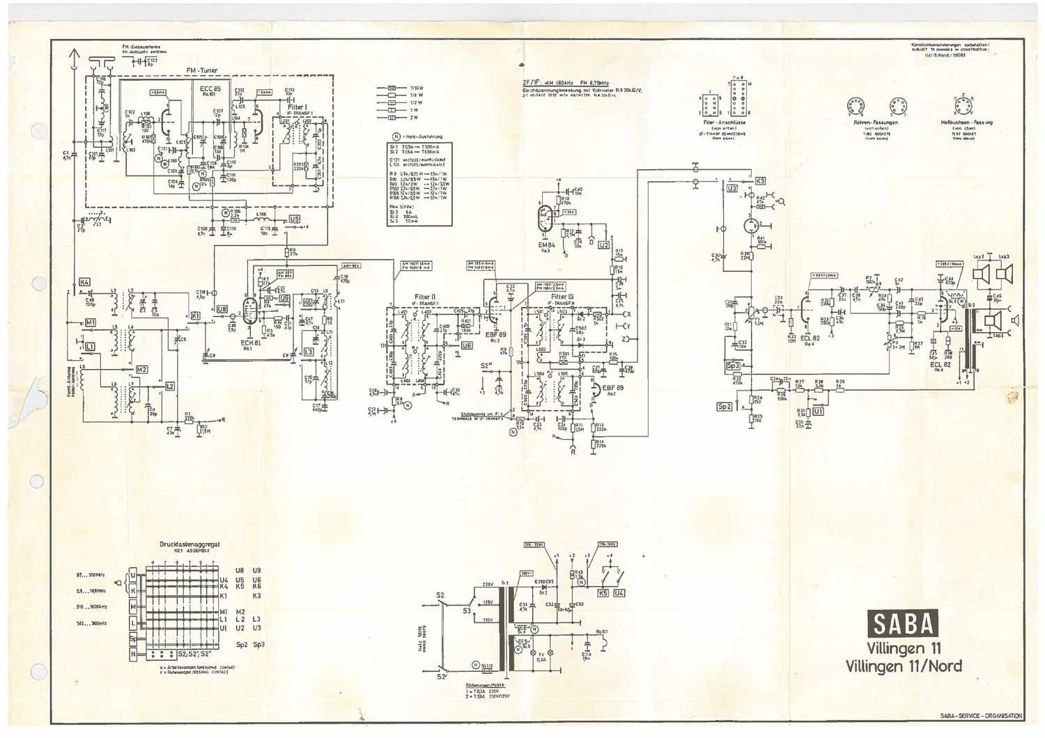
Saba villingen 11

This is the 7 pages manual for saba villingen 11.
Read or download the pdf for free. If you want to contribute, please mail your pdfs to info@audioservicemanuals.com.

Page: 1 / 7
left right
saba villingen 11

Extracted text from saba villingen 11 (Ocr-read)


Page 2

Abgleichanleitung flir SABA Villingen 11

Abglelch des AM-Telles

a) Automatrsche Schwundregeiung durch An'sgen ainer nie-
derohmlgen Spannungsquelle (z. B. Taschenlampen-Bat-
terie) von ca. 4.5 Volt an die MeBbuchsen Fl (-) und Y
(+) ausschalten.

b) Lautsprecher und NF-Voltmeter an die Ausgangsbuchsen
anschlleBsn.

c) Hohanregler suf LInksanschlag steien.

ZF-Abglelch 460 kHz

a) Druchtaste M drlIcken.

b) MeBsender (460 kHz, 30% ampl. mod.) fiber 10 nF an
das Steuerglttar der ECH 81 legen.

thtungl Durch Linksdrahen der Kopplungsschraube wird die

Koppiung der Filter verklelnsrt. durch Rechtsdrehen vergroa-

sert.

Filter Ill

1. Kopplung K 504/5 unterkrltlsch enstellen.

2. Belde Krese mit L 504 und L 505 out Maximum abgeichen

3. Erforderiichenfalls 1. und 2. wiederhoien.

4. Kopplung mit K 504/5 krltlsch einstelien (max. Ausgangs-
spannung),

Filter II

Kopplung mlt K 403/4 unterkmlsch elnstelien.

Belde Krelse ml! L 403 und L 404 auf Maximum abgle'chen.
Erforderllchenfails l. und 2. wiederholen.

Kopplung mit K 4034 krltlsch elnstelisn (max. Ausgangs~
spannung).

+99):-

ZF-Sperre 460 kHz

1. MeBsender fiber kfinstiiche Antenne (200 pF und 400 Ohm
In Serle) an Antennen-Buchse legen.

2. Drucktaste M drucken.

3. ZF-Sperre mi! L l auf Mlnlmum abgleichen.

Oszlllator-undVorkrelsabglelch

Kontrolie; Zeigerrechtsenschlag muB mlt der Skalenendmarke

uberelnstimmen; dabel muB dsr Rotor daa Drehkos bundig Im

Stator stehen.

MeDsender obsr kflnstllche Antenna an Antsnnen-Buchse le-

gen.

1a) Drucktaste K drilcken. Bel 7.2 MHz L 9 (Osz.) und L 2
(Vorkr.) auf Maximum abgleichen.

1b) Bel 15.2 MHz C 13 (0:31.) und C 3 (Vorkr.) suf Maximum
abgleichen.

1c) Erforderllchenfalls Ia) und 1b) wiedarholen.

2a) Druoktaste M drucken. Bel 570 kHz L 11 (Osz) und L 4
(Vorkr.) auf Maximum abglelchsn.

2b) Bel 1520 kHz 0 14 (052,) und C 6 (Vorkr.) auf Maximum
abglelchen.

2c) Erforderllchenfalls 2a) und 2b) wlederhoien.

3 J Drucktaete L drucken. Bel 190 kHz L 12 (Osz.) und L 7
(Vorkr.) auf Maximum abglelchen.

Abglelch des FM-Telles

a) Drucktaste UK drucken.

b) Voltmeter (HI 2 500 kOhm, 10 Volt-
Bereich) an die MeBbuchsen X und Y
anschlieBen.

c) Mlkroampersmeter mit Nuilpunkt In
der Mltte an die Melbbuchsen X. Y
und 2, gemtll) Schaltaklzze, anschlles-
sen.

ZF-Abglelch 6,75 MHz

MeBsander (6.75 MHz. unmoduliert. Ausgangskabel abge-
schlossen) fiber 1 nF an das kalte Ends von C 105 und
Masse Iegan. C 105 sowelt verstlmmen, daB die Hausch-
spannung am Voltmeter verschwlndet.

.(Empfanger soll dabel auf 92 MHz stehen).

Filter Ill (Ratlolllter)

1. MI! K 501/3 Filter entkoppaln.

2. Primerkreis mlt L 50I auf Maximum am Voitmetsr ab-
gialchen.

3. Sekundllrkrels mit L 503 auf Nuildurchlauf am Mikroam-
pare-Meter abglelchen.

Filter II

I. Kopplung mlt K 40132 unterkrltisch einsteilan.

2. Belde Krelse mlt L 401 und L 402 out Maximum am Volt-

meter abgielchen.

Erforderllchenfalls 1. und 2. wiederhoien.

4. Kopplung mlt K 4012 krltlsch einstellen (max. Spannung
am Voltmetar).

9

Filter I

1. Kopplung mit K 201:2 unterkritisch einstsllen.

2. Belde Krs se mlt L 201 und L 202 auf Maximum am Volt-
meter abgleichen.

3. Erforderiichenfails 1. und 2. wlederholen.

4. Koppiung ml! K 201 2 kritlsch slnstellan (max. Spannung
am Voltmetar).

Flltar III (Flatlofllter)

MeBaender jetzt 30% amplitudenmoduliaren.

1. Koppiung mlt K 5013 aowelt anziehen. bis die NF-Span-
nung an den Ausgangabuchsan ein Minimum errelcht. Dle
Spannung an den Mefibuchsen X-Y soll dabel etwa 10 Volt
betragen.

2. Primtlrkrais mit L 501 auf Maximum am Voltmeter nach-
gleichen.

3. Sakundarkreis mlt L 503 out Nulldurchlauf em Mikroam-
pare-Meter nachglelchen.

4. Erforderllchenfalls 1. bis 3. wiederholen.

Abglelch des FM-Tuners

UKW-MeBsender an Dipolbuchsen legen.

1a) Bel 85 MHz C 109 (Osz.) und 0 105 (Anodenkrels) auf
Maximum abglelchen.

1b) Bel 93 MHz L 104 (032.) und L 103 (Anodankreis) auf
Maximum abglelchan. (L 104 durch Verstelien des Ab-
stimmhebels, L 103 durch Kernversteilung).

2 ) Bel 92 MHz L 102 auf Maximum abgleichen (durch Kern-
verstellung).

3a) Anodenspannung der HF-Stufe abschalten (Brooke ab-
loten). Elngangsspannung auf ca. 0.5 mV arhfihen.

3b) Neutralisatlon mlt C 103 auf Minimum abglelchen.

3c) Anodenspannung der HF-Stufe wisdereinschslten (Brucke
anlfiten).

4 ) Zum gsneuen Abgleich I) und 2) wiederholen.

F

Alignment Instructions for SABA Villingen 11

AM-Allgnment

a) Eliminate AVC by applying about 4.5 volts from a low-
resistance battery to test points Fl (--) and Y (+).

b) Connect loudspeaker and output-meter to the output ter-
mlnals.

c) Turn treble control to left step.

460 kc IF Alignment

a) Press key M.

b) Connect a signal generator (460 kc, 30% ampl. mod.)
through a 0.01 mF. capacitor to the control gr1d of the
mixer tube ECH Bl.

Attention! The coupling of the IF transformers decreases by

turning the screw counter-clockwise and Increases by tur-

ning clockwise.

IF Transformer Ill

1. Adjust coupling subcritlcal with K 504.15.

2. Adjust both circuits with L 504 and L 505 to max.
3. If necessary repeat 1. and 2.

4. Adjust coupling critical with K 504/5 (max. output).

IF Translormer II

Adjust coupling subcritical with K 403/4.

Adjust both circuits with L 403 and 404 to max.

If necessary repeat 1. and 2.

Adjust coupling critical with K 403/4 (max. output).

PPPT

IF Trap 480 kc

1. Connect signal generator through dummy antenna (200
mmf. and 400 ohms In series) to antenna socket.

2. Press key M.

3. Adjust. IF trap with L 1 to min.

Allgnment oI Oscillator and Preaelectlon

Check: with pointer stop on right. pointer must, e at cor-

responding point on the dial. The rotor of the. var ble capa-

citor must fit flush In the stator. fiat? "5?-

Connect slgnal generator through dumm gdtenna to antenna

socket. 1

1a) Press key K. At 7.2 Ms adjust L 9 (sec) and L 2 (ant.)
to max.

1b) At 15.2 Ma adjust C 13 (osc.) and C 3 (ant) to max.

10) If necessary repeat la) and 1b).

2a) Press key M. At 570 kc adjust L 11 (osc.) and L 4 (ant)

to max. ) .

2b) At 1520 kc adjust C 14 (osc.) and C 6 (ant) to max.

2c) If necessary repeat 2a) and 2b).

3 ) Press key L. At 190 kc adjust L 12 (osc.) and L 7 (ant)
to max.

FM-Allgnment .

a) Press key UK.

b) Connect a voltmeter (HI 2 0.5 mag-
ohm, 10 volts full scale reading) to
test points X and Y.

c) Connect zero-centre microammeter to
test points X. Y and Z.

IF Alignment 6,75 Mo 5

Connect signal generator (6.75 Mc, unmodulated, output cable
matched) through 1000 mmf. to low side of C 105 and chassis.

fl


Datune C 105 until the noise voltage disappears at the volt-
meter (For this set receiver to 92 Mc).

IF Transformer III (Ratio-Detector)

1. Adjust coupling subcritical with K 501/3

2. Adjust primary circuit with L 501 to max. at voltmeter.

3. Adjust secondary circuit with L 503 to zero at micro-
ammeter.

IF Transformer ll

1. Adjust coupling subcrltlcal with K 401/2.

2. Adjust both circuits with L 401 and L 402 to max. at volt-
meter.

If necessary repeat 1. and 2.

4. Adjust coupling critical with K 401/2 (max. at voltmeter).

9

IF Transformer l

1. Adjust coupling subcrltlcal with K 201/2.

2. Adjust both circuits with L 201 and L 202 to max. at volt-
meter.

3. If necessary repeat 1. and 2. '

4. Adjust coupling critical with K 201/2 (max. at voltmeter).

IF Tranelormer III (Ratio-Detector)

Signal generator must now be 30% ampl. mod.

I. Tighten coupling with K 501/3 until the audio voltage at
the output reaches Ita min. The voltage between test po-
Ints X and Y should be about 10 volts.

2. Correct adjustment of primary circuit with L 501 to max.
at voltmeter. w

3. Correct adjustment of secogdary circuit with L 503 to zeror
at mlcraamrneter.

4. If necessary repeat 1. to 3..

Alignment oftha FM Tuner

Connect VHF signal generator to dipole sockets.

1a) At 86 Mc adjust C 109 (osc.) and C 105 (r. f.) to max.

1b) At 98 Mc adjust L 104 (osc.) and L 103 (r. f.) to max.
(L 104 by shifting the tuning rod. L 103 by shifting the
core). X '

2 ) At 92 Mc adjust L 102 to max. (by shifting the ore).

3a) Cut off plate voltage of r. f. ampl. (unsolder connection).
increase Input voltage to about 0.5 mllllvolt.

3b) Adjust neutrallaatlon with C 103 to min. '

3c) Fla-solder connection.

4 ) For exact alignment repeat 1) and 2).

O
u

cu

[M
5 e:
1.1 not I
6

G

- ooo

memoirs

e.~.t.4 x. up. um Vawnun 7