Saba transamerika 16 service manual

This is the 14 pages manual for saba transamerika 16 service manual.
Read or download the pdf for free. If you want to contribute, please mail your pdfs to info@audioservicemanuals.com.

Page: 1 / 14
left right
saba transamerika 16 service manual

Extracted text from saba transamerika 16 service manual (Ocr-read)


Page 1

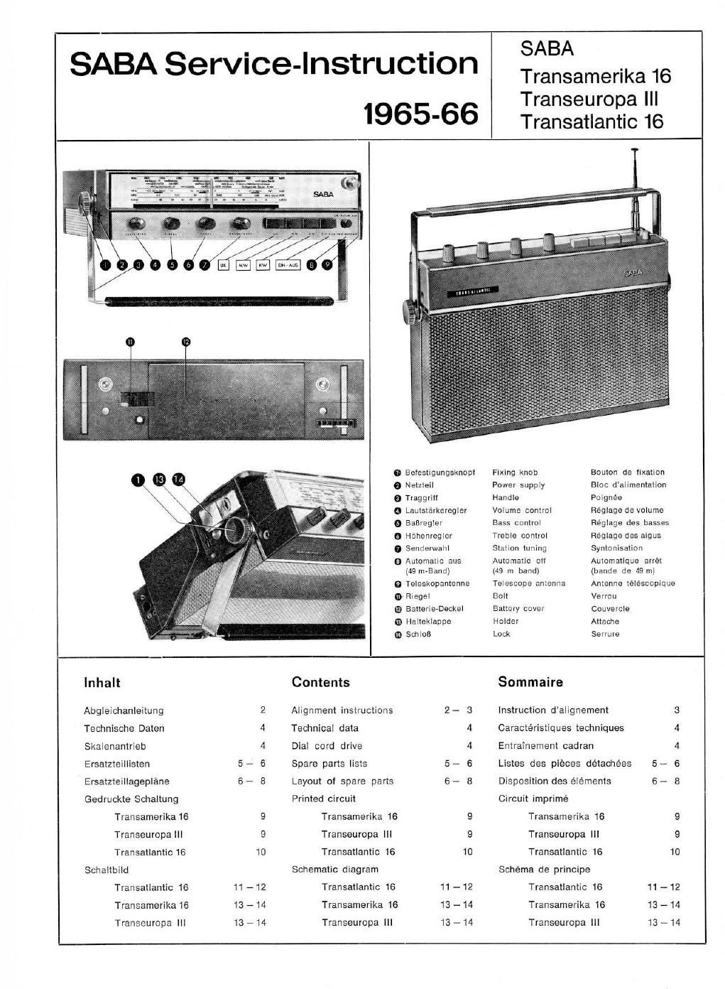
SABA Service-Instruction
1965-66

SABA

Transamerika 16
Transeuropa |l|
Transatlantic 16

runl n-v

o Batestigungsknopl

Fixing knob Eouton de llxallon

o Netzleil Power supply Bloc d'alimentalion
9 Traggri" Handle Poignée
o Laulst'arkeregler Volume control Réglage de volume
6 Baflregler Bass control Réglags des basses
o Héhenregicr Treble control Héglaga des aigus
0 Senderwanl Slalion tuning Synlonisalion
0 Automatic aus Automatic on Automatique arrét
(49 m-Band) (49 in band) (bande as 49 m)
0 Telsskopantenna Telescope anianna Antenna téléscopique
0 Riegel Bolt Verrou
Q aattarie-Deckel Battery cover Couvercle
0 Halteklappe Holder Attache
@ sailor: Lock Serrure
lnhalt Contents Sommaire
Abgleichanleitung 2 Alignment instructions 2- 3 instruction d'alignement 3
Technische Daten 4 Technical data 4 Caractéristiques techniques 4
Skalenantrieb 4 Dial cord drive 4 Entrainement cadran 4
Ersatzteillisten 5- 6 Spare parts lists 5- 6 Listes des pieces détaohées 5- 6
Ersatzteillageplane 6- 8 Layout of spare parts 6- 8 Disposition des éléments 6- 8
Gedruckte Schaltung Printed circuit Circuit imprirné
Transamerika16 9 Transamerika 16 9 Transamerika 16
Transeuropa Ill 9 Transeuropa III 9 Transeuropa IlI
Transatlantic 18 10 Transatlantic 16 10 Transatlantic 16 10
Schaltbild Schematic diagram Schéma de principe
Transatlantic 16 11 - 12 Transatlantic 16 11 - 12 Transatlantic 16 11 - 12
Transamerika 16 13 - 14 Transamerika 16 13 - 14 Transamerika 16 13 - 14
Transeuropa Ill 13 - 14 Transeuropa III 13 - 14 Transeuropa Ill 13 - 14

Page 2

Abgleichanleitung

Alignment Instructions

Zum Abglelch mufl lm allgamelnen der Laut-
sprecher ausgebaut warden.

EInItellen dee Ruheetrome

ElnalelIUng eel einer Betteriespennung von 7 V
vornehmen. ohne Eingangsslgnal. Lautstéirke-
regler zugeoreht.

P m

Es dart nur die ElN-AUS-Taste gedrflckt sein.
Raglar P 404 so einstellen. use an der Mittel-
anzapiung des Treibertraios Tr. 401 0.15 V ge-
gen + B steht.

Abglelch doe AM-l'ells

a) GIelchspannungs-Rohrenvoltmeter
MeBstllte D und St ansohlieeen.

b) HF-Si nal so einstellen. daB die Spannung
am R hrenvoltmeter ca. + 11.1 V betrigt.

an die

ZF-Abglelch 400 kit:

a) Drucktuete M drflcken. Drehko ganz ein-
drehen.

b) MeBsender (unmodullerl) fiber 0.1 pF an
die Basis des Mischlranaislors 1 2 legen.

c) ZF-Sperre mit L71 (Filter ll) verstimmen
(Kern Fliottung Drucirplatte).

Filler VII
Krels mit L 385 out Maximum abglelmen.

Filter VI

lede Krelse mit L 285 und L 286 aui Maxi-
mum abgleichen.

Filter IV

Eelde Krelse mit L 85 one L 06 aut Maximum
abgieiohen.

ZF-Sporre 450 kHz

ZF-Sperre mit L 71 (Filter II) eut Minimum
abgleichen.

Oezllntor- und Vorkreleebgielch

Kentrolle: Zeigerrechtsanschlag muB mit der
Skelenendmarke iihereinstlmmen; dabel muB
thiar Rotor des Drehkes biindig lm Stator ete-
en.

Meesender mittela eines Ferritstabes mit Spule
lose aui die Ferritentenne koppeln (Abstand
mindestens 10 cm).

Trunumerlkl 1G - Trenseuropa III

1) Drudttaste L drunken. Bei 190 kHz L 14
(031.) und L 1 (Vorkr) eut Maximum at»
gleiohan.

2a) Drucklaste M driicken. Bel 570 kHz L 15
(082.) out Maximum abgleichen.

20) Sci 1520 kHz 037 (051.) aul MaXImurn ab-
glelchen.

2c) Ertorderllchenlalls 23) und 2b) wieoerholen.

3) Lautsprecher einbauen.

4) Drucktaste L driidten. Bel 190 kHz L 7
(Ant) aui Maximum abgleichen.

5a) Drucktaste M drucken. Bei 570 kHz L 4
(Ant) aut Maximum abglelmen.

5b) Bel 1520 kHz 0 4 (Ant) aut Maximum ab-
gleichen.

5c) Ertorderlichsnlalls 5a) und 5b)wiederholen.

Jetzt Empianger In die Autohalterung sinschie-
ben. MeBaender tiber kunstiiete Antenne
(Fig. 1) an Antennenbuchse legen. Antennen~
trimmer (C 804) in der Autohalterung in Mittel-
stellung bringen.

6) Drucktaste M drilcken. Bei 1 MHZ L 10 (Va-
riometer) aui Maximum abgleichen.

7) Drucktaste L drflcken. Bei 150 kHz L 9 aul
Maximum abgleichen.

Transatlantic 16

1a) Drucktaste K drfioken. Eel 7 MHz L 18
(031.) an! Maximum abgleichen.

1b) Bei 11 MHz 0 35 (Cal) aul Maximum ab-
glelchen.

1c) Ertoroerllchenfulla la) und 1b) wiederholen

2a) Drucktaste M driicken. Bei 570 kHz L 15
(032.) aut Maximum abgleidten.

2b) Bet 1520 kHz C 37 max.) aui Maximum abA
gieidien.

2c) Ertorderlichenialls 2a) und 2b)wlederhoien.

3) Laulsprecher einbauen.

4a) Bet 570 kHz L 5 (Ant) aul Maximum ab-
gleldten.

4b) Bel 1520 kHz C 4 (Ant.) aul Maximum ab-
gleimen.

to) Ertorderllchenlalls da)und 4b)wlederhoien.

Se) Druckteste K drflcken. Bel 11 MHz 0 35
(051.) aut Maximum nachgleichen.

5b) Bel 7 MHz L 3 (Ant) aut Maximum abglei-
men.

6) Druoktasten K um! 49 m-Band drunken. Bel
5.1 MHz 0 19 (052.) und C 3 (Ant) aut
Maximum aoglareten.

Jetzt Emptanger in die Autohalterung ainsdtle-

ban. MeBsenoer Dber kunstllche Antenne (Fig.

1) an Antennenbuchse Iegen. Antennentrim-

mer (C 804) In der Autohalterung in Mittel-

steliung bringen.

7) Druektaste M orucken. Hal 1 MHz L 10
(Variometer) aui Maximum abglelchen.

Abglelch des Flt-Tells

a) Hohrenvoltmeter an die MeBstlfte X und Y
anschlieBen.

b) Mlkroampere-Meter mit Null unkt in der
Mitte In Serle mit elnem Woerstand von
(1300 kg an die MeBstilte St und M anschllev
en.

c) NF-Voltmeter parallel zum Lautaprecher

legen.
d) Dmcktaste UK driioken.
e) Emplinger aul ca. 88 MHz stellen.

ZF-Ahglelch 10.1 Mil:

MeBsender (unmodulierl) an MaBpunkt ZF Ia-
gen. Spennung am Hohrenvoltmeter soll baim
esamten Ahgleioh etwa 1.5 V betragen.
auschspannung durm gsringes Rechtsdrehen
von C 108 verkleinern.

Flller VII
1) Filter durch Llnksdrehen von K 381/3 enl-
koppeln.

2) Primarkrels mit L 381 out Maximum am
RVM abgleichen.

3) Sekundfirkreis mit L 363 eui Nulldurotlaul
am Mikro-Ampere-Meter abgleidten.

Meltsender ietzt lrequenzmedulieren (Hub ca.
20 kHz).

4) Kop lung mit 331/3 soweit anziehen. bis dle
NF- pannung vom Maximum aus um 10%
gaiallen let.

5) Sekundarkrels mil L 303 aul Nulldurchlaui
am Mikro-AmpereMeter nachgleichen.

6) Primerkrele mit L 381 out Maximum am
FlVM nachgleiohen.

MeBsander jetzt 30']. amplitudenmodulleren.
7) P 301 am NF~Minimum abgleichen.

8) Sokundarkreis mlt L 363 out Nulldurd'tlaui
nachgleichen.

9) Primarkrels mit L 381 But Maximum naoh-
gleiohen.
Filter V

Kreis mil L 251 aul Maximum am FIVM ab-
gleichen.

Filter III
1) Kopplung durch Linksorehen von K 01/3
unterkritisdi einstallen.

2) Beide Krelse mit L 81 und L K? aul Maxi-
mum abgleichen.

3) Erlorderlichenlulls 1) und 2) wiederholen.

4) Kopplung durch Flechtsorahan von K 01/3
kriliso,h elnstallen (max. Spannung am Voit-
meter.

Filter ll
Kleis mit L 72 am Maximum abgleichen.
Filler I

Beide Kreise mit L107 und L 108 aut Maximum
aogleichen.

Ahglelch den Fill-Tuners

UKW-MeBsender an Antenneneingang legen.

1) Bei 90 MHZ C 123 £051.) und 0 108 (Vorkr.)
aul Maximum am VM abglelchen.

2) Bet 100 MHz L 104 (052.) and L 10:1 (Vorirr.)
aul Maximum am RVM abgleiaren.

3) Ertorderlidtenlalls 1) und 2) wiederholen.

Mit C 112 wird dla Schwingspannung des 0s-

zillators eingestellt (70-100 mV zwischen Emit»

ler von T 102 und Masse). Braucht normsler-

welse nicht abgeglichen zu warden.

RI¢R2:80.D.

I- ______ 7

RI 2 R2 cl1 I
Mcflsendar I 159 c2 l
StGNAL 65mm : 60p 1
I

______ _I

Fig. 1

In general. the loudspeaker must be removed
belore the receiver is aligned.

Adjustment at steady-state Current

The adjustment should be carried out with a
battery voltage at 7 volts without any input
signal. with the volume control turned down.

P 40

Only the ElN-AUS (ON-OFF) button should be
pressed. Adjust potentiometer F 404 so that
the center tap oi the secondary oi driver
translormer Tr. 401 Is at a potential at 0.15
volts with respect to the B plue voltage.

Allgnement oi the AM Part

a Connect dc VTVM to test point: D and St.

b Adjust RF signal so that the VTVM read:
about + 0.1 volt.

IF Alignment. 60 Ki:

3) Press button M. Turn tuning condenser to
the completely closed position.

b) Connect signal generator, unmooulated.
through a 0.1 ml capacitor to the base at
mixor transistor T 2.

c) Disable IF filter with L71 (IF Iranslormar ll).

IF Transiormer VII
Align circuit for max. with 355.

IF Tramiorrner VI
Align both circuits lor max. with L 235 and
L 286.

IF Transtormlr IV
Align both circuits tor max. with 85 and L 05.

IF Trap. m Kc
than IF trap (1F lransiormer ll) tor min. with

Alignment ol 0 ecillator and

P r e l 0 ct l o n

Check. with pointer stop on right. pointer must
be at corresponding point on the dial. The
rotor oi the variable capacitor must be tluah
in the stator.

Couple signal generator loosely to the ierrite
antenna by means oi a iarrite rod with a wind-
ing (at a distance at at least 10 cm. 4 inches).

Trans-marlin lo - Treneeurope Ill

1) Press button L. Align L to (osc) and L 7
(ant) tor max. at 100 Kc.

2a) Press button M. Align L 15 (osc.) ior max.
at 570 Kc.

2b) Align C 37 (osc) tor max. at 1520 Kc

2c Repeat 23) and am) It necessary.

a) Reinstall loudspeaker.

4 Press button L. Align L 7 (ant) tor max.
at 190 Kc. .

5a) Press button M. Align L 4 (ant) lor max.
at 570 Kc.

5b Align c 4 (ant. tor max. at 1520 Kc.

5c Repeat as) an so) It necessary.

Now insert the receiver In the car adapter

mount. Connect signal generator to antenna

socket through dummgoantenna (Fig. 1). Turn

antenna trimmer (c ) in the car adapter

mount to Its center position.

6) Press button M. Align L 10 tor max. at

1 Me.
7) Press button L. Align L 9 tor max. at
190 Kc.

Transatlantic 10
1a) Press button K. Align L 16 (osc.) tor max.
at 7 Mc

1b) Align C 35 1030.) for max. at 11 Mo.

19 Repeat 1a) and 1b) it necessary.

23 Press button M. Align L 15 (can) lor max.
at 570 Kc.

2b) Align C 37 (osc.) for max. at 1520 Kc.

2c) Repeat 2:) and 2b) it necessary.

Trannmerllra 18

mi "5 Tranuuropl ill

have... a. a. .0... Anti