Saba mi 212 service manual 2

This is the 4 pages manual for saba mi 212 service manual 2.
Read or download the pdf for free. If you want to contribute, please mail your pdfs to info@audioservicemanuals.com.

Page: 1 / 4
left right
saba mi 212 service manual 2

Extracted text from saba mi 212 service manual 2 (Ocr-read)


Page 1

SABA HiFI 167

integrated stereo

Service-Schaltbild amplifier MI 212

Service circuit diagram
Documentation technique
Schema di servicio

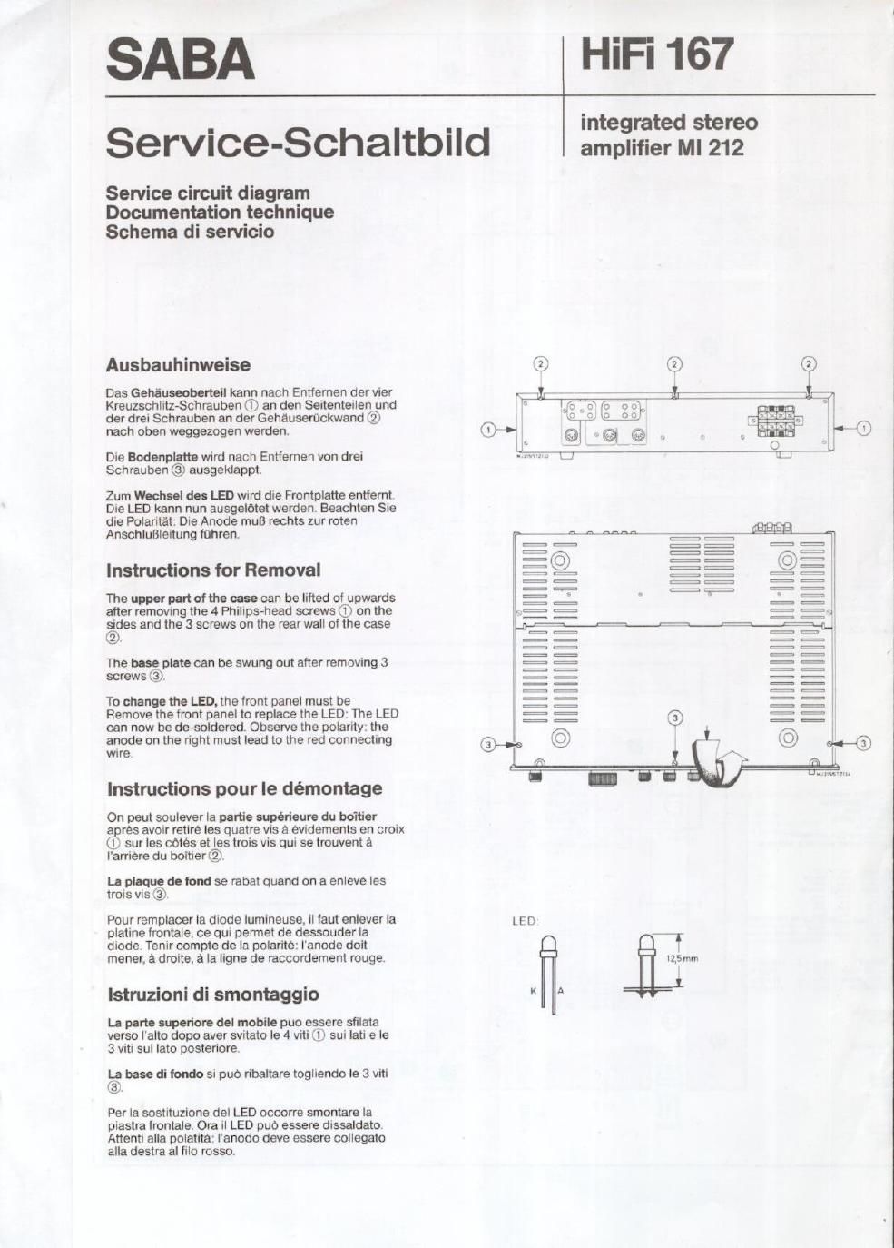
Ausbauhinweise

Das Gehiuseobemll kann nach Entfemen der vier
KreuzschlltzSchrauben (D an den Seitenteilen und
der drei Schrauben an der Gehauserockwand ®
nach oben weggezogen warden.

Die Bodonpllth wird nach Entfemen von drei
Schrauben © ausgeklappt.

Zum Wochul do: IE) wird die Frontplatte entfemt.
Die LED kann nun ausgelotet warden. Beachten Sie
die Polaritet: Die Anode muB rechts zur roten
Anschlulileltung fohrent

Instructions for Removal

The upper part oi the use can be lifted ol upwards
after removing the 4 Philips~head screws ® on the
Eisjes and the 3 screws on the rear well of the case

2 .

The hose plate can be swung out after removing 3
screws (3).

To change the LED. the front panel must be
Remove the front panel to replace the LED: The LED
can now be de-soldered. Observe the polarity: the
anode on the right must lead to the red connecting
WIIBV

Instructions pour le démontege

On peut soulever la panic superieure du bolder

a res avoir retire Ies quatre vis a evidements en croix
I sur les notes et les trois vis qui se trouvent a

Iarriere du boltier @.

L- plaque do tend se rabal quand on a enleve les
trois vis ©

Pour remplacer la diode Iumineusa, il taut enlever Ia L E D

platine frontale, ce qui permet de dessouder la ,7
diode Tenir oompte de la polarite: l'anode dolt f
mener. a droite, a la ligne de raccordement rouge. izsmm

lstruzioni di smontaggio * A

La part- nuporiorl del mobile puo essere sfilata
verso Ialto dopo aver svitato Ie 4 viti (I) sui lati e le
3 viti sul lato posteriore.

bl bone di fondo si puo ribaltare togliendo la 3 viti
3 .

Per la sostituzione del LED occorre smontare la
piastra lrontale. Ora il LED puo essere dissaldato.
Attenti alla polatita: lanodo deve essere collegato
alla destra al filo rosso.