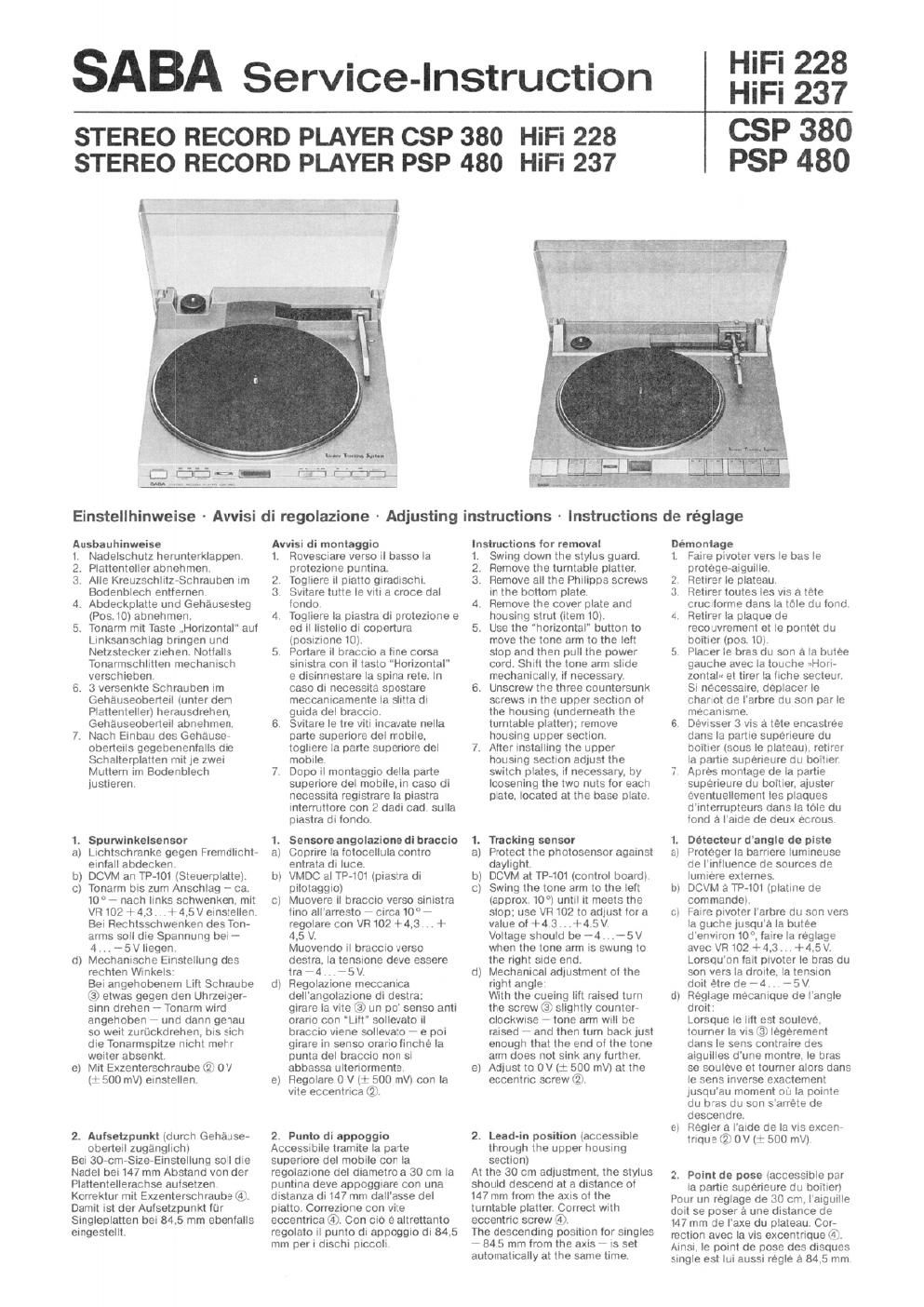
Saba csp 380 psp 480 service manual

This is the 9 pages manual for saba csp 380 psp 480 service manual.
Read or download the pdf for free. If you want to contribute, please mail your pdfs to info@audioservicemanuals.com.

Page: 1 / 9
left right
saba csp 380 psp 480 service manual

Extracted text from saba csp 380 psp 480 service manual (Ocr-read)


Page 1

SABA Service-Instruction

HiFi 228
HiFi 237

STEREO RECORD PLAYER CSP 380 HiFi 228
STEREO RECORD PLAYER PSP 480 HiFi 237

CSP 380
PSP 480

J

Einstellhinweise - Avvisi di regolazione ~ Adjusting instructions ~ Instructions de réglage

Ausbauhinweise

1. Nadelschutz herunterklappen.

2 Plattenteller abnehmen,

3 Alle Kreuzschlitz»Schrauben im
Bodenblech entlemen.

d Abdeckplatte Lind Gehausesteg
(P05. 10) abnehmen

5 Tonarm mit Taste .,Horizontal" aui
Linksanschlag bringen und
Netzslecker Ziehen. Nottalls
Tonarmschlitteh mechanisch
verschieben

6. 3 versenkte Schrauben im
Gehauseoberteil (unter dem
Plattentellerl herausdrehen.
Gehauseoberteil abnehmen.

7 Nach Einbaii des Gehause-
oberteils gegebenenlalls die
Schalterplatten mit ie zwei
Muttern im Bodenblech
justieren.

1. Spurwirikelsensor
Lichtschranke gegen Freiiidlicht-
einlall abdecken

b) DCVM an TP-lOt (Steuerplatte).
c) Tonarrn bis zum Anschlag - ca.
10° - nach links schwenken, mit
VR 102 + 4.3 ..+ 4.5 V einstellen.
Bei Rechtsschwenken des Ton-
arms soil die Spannung bei -

4 75V liegen

Mechanische Einstellung des
rechten Winkels

gel angehobenem Lift Schraube
<3) etwas gegen den Uhrzeiger»
sinn drehen 7 Tonarm wrrd
angehoben - und oann genau
so weit zurtickclrehen, bis sich
die Tonarmspitze nicht mehr
weiter absenkt.

Mit Exzenterschraube (2i 0V

t' 500 mV) einstellen.

E

d

e

2. Autsetzpurikt tdurch Gehause-
oberteil zuganglich)
Bel 30-cm-Size-Einstellung soil die
Nadel oei 147 mm Abstand von der
Plattentellerachse auisetzen.
Korrektur rriit Exzenterschraube @l.
Damit ist der Autsetzpunkt liir
Singleplatten bei 84.5 mm ebenlalls
eingestellt.

Awisi di montaggio

1. Rovesmare verso il basso la
protezrone puntina.

2. Togliere II piatto giradischi.

3 Svitare tutte le viti a croce dal
londo.

4. Togliere la Diastra di protezrone e
ed il listello di copertura
tposizmne 10)

5. Portare i| braccio a hne corsa
sinistra con it taste Horizontal
e disinnestare Ia spina rate. In
case or necessita spostare
rrieccanicamente la slitta di
guida del Draccio.

G. SVItare le tre viti incavate nella
pane superiore del mobile.
togliere Ia parte supenore del
mobile.

7 Dope il montaggio delta parte
supenore del mobile, in case di
necessita registmre la piastra
interruttore con 2 dadi cad sulla
piastra di londo,

1. Sensors angolazione di braccio
Coprire la iotocellula contro
entrata oi Iuce.

VMDC al TP-tot (plastra di
pilotaggio)

Muovere il braccio verso sinistra
lino allarresto 7 circa 10" -
regolare con VFt102 +4.3 .. +
4.5 V.

Muovendo il braccro verso
destra. la tensrone deve essere
tra - 4 - 5 V.

Regolazlone meccanica
dellangolazmne di destra:
girare la vite (a) un po sense anti
orario con Lift" sollevato il
braccno viene sollevato - e poi
girare In senso orario iinche Ia
punta oel braccm non si
abbassa ulteriormente

Regolare 0 V (i: 500 mV) con la
vite eccentrica (it

E

b

c

d

e

2. Punto di appoggio

Accessmile tramite la parte
superiore Get mobile con la
regolazione del diametro a 30 cm la
puntina deve appoggiare con una
distanza di147 mm dall'asse del
piatto. Correzione con Vite
eccentrioa 6!). Con cio e atirettanto
regolato il punto di appoggio di 84.5
mm peri dischi piccoli

Instructions for removal

1. Swing down the stylus guard.

2. Remove the turntable platter.

3. Remove all the Philipps screws
in the bottom plate.

4. Remove the cover plate and
housing strut (item 10)

5. Use the horizontal" button to
move the tone arm to the left
stop and then pull the power
Cord. Shift the tone arm slide
mechanically, it necessary

6. Unscrew the three countersunk
screws in the upper section at
the housrng tunderneath the
turntable platter); remove
housrng upper section

7 Alter installing the upper
housing section adjust the
switch plates, it necessary. by
loosening the two nuts lor each
plate. located at the base plate

1. Tracking sensor
a Protect the photosensor against
daylight.
bl DCVM at TP-101 (control board).
cl Swing the tone arm to the tall
(approx, 10°) until it meets the
stop, use VR 102 to adiust tor a
value at +4 3 ..+4.5V
Voltage should be 74 , 75V
when the tone arm is swung to
the right Side end,
Mechanical adjustment of the
right angle:
With the cueing |ill raised turn
the screw (3V slightly counter
clockwise 7 tone arm will be
raised 7 and then turn back just
enough that the end of the tone
arm does not sink any lurther
Adiust to 0V t: 500 mVl at the
eccentric screw (2.

d

e

2. Lead-in position (accessrble
through the upper housing
section)

At the 30 cm adjustment, the stylus

should descend at a distance oi

147mm from the axis oi the
turntable platter gorrect wrth
eccentric screw V3).

The descending position tor singles

- 84.5 mm lrom the axis 7 is set

automatically at the same time.

Démontage

l Faire pivoter vers to has le
protegeaiguille,

2 Retirer le plateau.

3. Retirer toutes les VlS a tete
crucllorme dans la tote du lond.

4 Retirer la plaque de
recouvrement et le pontet du
boitier (pos lot

5 Placer le bras on son a la butee
gauche avec la touche -»Hori-
zontalu et tirer la liche secteur
Si necessaire, deplacer le
chariot Ge larbre du son par le
mecanisme,

6 Dewsser 3 yrs a late encastree
dans la name superieiire du
boltier [sous la plateaul. retirei
la panie supeneure du boitier.

7 Apres montage oe la panie
supeneure du boilier. ajiister
eventuellement les plaques
d'Interrupteurs dans la tote du
lond a lame de deux ecrous.

1. Detecteur dangle de piste
Proteger la barriere lumineuse
de Iiniluence de sources de
lumiere externes.

DCVM a TP-tOl (platine de
commandel

Faire pivoter larbre du son vers
Ia guche iusqua la butee
d'environ 10, iaire la reglage
avec VR102 + 4.3 + 4.5 V
Lorsquon tail pivoter le bras du
son vers la drone. la tension
doit etre de -4 .-5V
Reglage mecanique de l'angle
omit:

Lorsque le lilt est souleve.
tourner la vis Cir legerement
dans le sens contraire des
aiguilles dune montre. le bras
se souleve et tourner alors dans
le sens inverse exactement
Jusqu'au moment ou la Dointe
du bras du son s'arrete de
descendre

Reglera I'aide de la vrs excen-
trique 2? 0V it 500 mVi

3,

D

c

d

e

2. Point de pose (accessible par
la partie superieure du bcitier)
Pour un reglage de 30 cm. l'aiguille
doil se poser a une distance de
147 mm de l'axe du plateau Cor-
rection avec la vis excentnque 14).
Ainsi. to point de pose des disaues
Single est Iui aussi regle a 84.5 mm

Page 2

Ahb.1 CSP380:
IllustrA
Fig.1 .f
Fig.1

3. Liflhohe (nur CSP 380)

Bei angehobenem Lilt wird mi!
Schraube t1) der Abstand zwischen
Plattenteller und Abtastnadel aul ca.
8 mm eingestellt.

2. Nenndrehzahl tdurch Boden-
platte zuganglich)

at Pilch-ControI-Regler aul Millet-
stellung

b) Mit Hille oer Stroboskop-
Anzeige 45 U/rnin.mitVR1 bzw.
33V: U/min. mil VR 2 einslellen.

5. Wechsel des Mikroscheltere
Beim Einbau des Mikroschatters 8?
(Pos. Nr, St is! daraut zu achten. daB
bet stromlosem Elektromagnet. d h
bet angehobenern Lilt. die Blatt-
kontakte geschlossen sind.
Andernlalls sind die .,Lilt< und
..Horizontal-Funktionen blockiert,

6. Wechsel dos Etektmrnagneten
Mi! Montageschrauben Hub aul

2 . , . 2.5 mm einstellen (Slehe

Abb. 2)

Priitung Positionslensor
a) Tonarm in Ruheposition.
b) DCVM an JL106.

Punk! 2 'l- 5 V

Punk! 3 0 V

Punk! 4' 0V

Priitung Elektromagnet (Lift)

Gleichstromwiderstand

BO . . . 90 Ohm

at DCVM zwtschen 13 und 14
(CNP 138],

b) Nach Dnicken der Taste .Litt
(Absenkeni nach einem 24 V-
Impuls (ca 0 5 s) mull die
Spannung bei 12V liegen und
der Elektromagnet anziehen,

c) Nach wiederholtem Drucken
(Anheben) 0V,

Prutung Schlittenrnotor
DCVM an CNP102.Punkt6:
Linkslaul' - 7 5 V
Rechtslaul + 7.5 V

Auswechseln der Abtastnadol
Nadeleinschub nach unten
abziehen.

Auswechseln des Abtastsystems
Zwei Schraunen an der Unterseite
des Tonarms Ibsen. Abtastsystem
nach vorne herauSZIehen -
gegebenenlalls Zuleitungen durch
das Tonarrnlager nachschieben.
Die Farben dieser Lettungen haben
lolgende Bedeuturig'

Weill .. L+ linker Kanal

Blau = L7 linker Kanal/Masse
Rot = R+ rechter Kanal

Grim - R- rechter Kanal/Masse

Auflagegewicht 1.5 p (CSP 380i
Einstellung mil Tonarrnwaage.
Nach Losen der Schraube seltlich
iin Balancegewicht kann dieses
verschoben werden.

3. Altezza di solicvamento

(CSP 380)
Con Lift" sotlevato. si regola con la
Vite Ll) Ia distanza tra piatto e testina
su circa 3 mm,

4. Giri nominali (accessibili tramlte
la piaslra di londo)

Ftegolatore Pitch Control su
posizlone mediana.

Regolare osservando l'lndica-
zione stroboscopia con VR 1 su
45 gin/min. nspettivamente con
VR 2 su 331/; gin/min

a

b

5. Soatituzione dot micro-
interrutore
Nel montagglo det microinterrutore
$2 (posizione nr. 9) e da osservare
one i contatti svano chiusi con elete
tromagnete senza ccrrente, che
vuole dire con Litt solievato. In case
contrario le lunzmni "Lift" e
Horizontal" sono bloccate,

6. Soetituzione dell'elettro-
magnete

Ftegotare Ia corsa con la viti di

montaggio su 2, .2,5 mm tvedi

illustr 2t

Controtlo sensore posizlone
a) Braccio in oosizione di riposo.
bl VMDC su JL 106.

Punto 2 t- 5 V
Punto 3 O V
Punto 4 0 V

Controllo elettromagnete (Lift)
Resistenza continua 60. .90 Ohm.
at VMDClra13 e14tcNP138t

b) Dopo la pressione del tasto Lilt
tdiscesal' dopo un impulse di
24V (ca 0.5 st la tensione deve
essere so 12 V e l'elettromagnete
deve lavorare.

Dope ripetute pressioni
(solievare). 0 V,

c

Controllo slitto motore
VMDC al CNP102, punto 6:
Corsa sinistra * 7.5 V
Corsa destra. + 7.5 V

Sostituzione delta puntine
Slilare verso il basso il supporto
punlina.

Sostituzione del sistema di
rivelamento

Allentare Ie due Viti sul lato interiore
del braccio, slilare in avanti il
Sistema di nvetamenlo * In case di
necessna. spingere I lili che
attraversaiio i| cuscinetto det
bracc-o

I colon quest. lili name it seguente
signilicato:

Btanco - L+ canale di sinistra

Blu - L- massa canale di sinistra
Rosso - R+ canale di destra

Verde - R- messa canale di destra

Peso d'appoggio 1.5 p (CSP 380)
Taratura con dinamometro. ll con»
tropeso si sposta dopo aver
allentato la sua vile laterals.

3. Cuelng lift height (OnlyCSP 380)
With the cueing lift raised. used the
screw (D to adjust the clearance
between the turntable and the
stylus lor approx. 8 mm,

4. Nominal speed (accesrble)
through the bottom plate)

a) Set the pitch control at its center
position.

b) Usmg the stroboscope as a
gauge. set tor 45 RPM with VR l
and tor 33% RPM with VR 2.

5. Changing out the microswitch
When installing the $2 microswitch
(item No.9) insure that the teat
contacts are closed when the
selenoid IS deenergized, L8,. when
the cueing tilt is raised. OtheMise
the lift' and Horizontal" lunctions
wIll be blocked

6. Changing out the solenoid
Use the mounting screws to set the
stroke length at 2 to 2.5 mm (see
lig. 2t.

Checking position sensor
a) Tone arm in its rest position,
bl DCVM at JL 106.

Test point 2: + 5 V

Test point 3: 0 V

Test point 4' 0 V

Checking solenoid (cuelng lift)

DC resistance. 80 to 90 Ohms.

a) DCVM between 13 and 14
(CNP138)

b) After depressing the lit!" button
(loweringt:
Following a 24 V pulse (approx.
0 5 s) the voltage must be at
12V. pulling up the selenoid,

ct After pressing again (raise): 0 V.

Checking the slide motor
DCVM at CNP 102. test point 6:
Traversing to the left a 7.5 V
Traversing to the right: + 7.5 V

changing out the stylus
Pull the stylus insert downwards.

Changing out the cartridge
Loosen the two screws on the
underside ot the lone arm; pullout
cartridge towards the lront. It may
be necessary to push the
connecting leads through the
tonearm bearing to provide
sullicient stack.

The colours at these wires have the
lollowing meanings:

White - L+ let! channel
Blue - L- lett channel/ground
Red - R+ right channel

Green = R- right channel/ground

Tracking force 1.5 p (CSP 380i
Adjustment with lone arm balance.
The counterweight can be moved
alter loosening the lateral screw

Abb. 2

Kontakte geschlossen

Instr. 2 Contatti chiusi
Fly. 2 Contacts closed
Fig. 2 Contacts tonnes

2...2.5mm

3. Hauteur du tilt

(seulement CSP 380t
Lorsque te litt est souteve. regler
avec la vis (D I'ecart entre la plateau
et l'aiguille de lecture a 5 mm env.

4. Nomhre nominal do tours
(accesible par la plaque de
lond)

at Regleur Pitch Control en
position medians.

b) Regler a tame de I'affichage du
stroboscope 45 t avec VR 1 et
33v: t avec VR 2.

5. Echange du microrupteur
Lors du montage du microrupteur
$2 (pose). veiller a ce oue tes
contacts a lames soient lermes
Iorsque Ielectroaimant nest pas
sous tension. c'est-a-dire Iorsque
ie litt est souleve. Sinon. les
lonctions nliltu et "horizontal" son!
bloouees.

6. Echenge do I'electro-aimant
Regler Ia levee a 2 . . . 2.5 mm avec
les vis de montage (voir tig.2).

Controls du detecteurde position
a) More du son en posde repos.
bl DCVM 3 JL 106.

Point 2' + 5 V

Point 3 O V

Point 4: 0 V

Contrble do l'étnctro-elmont (tilt)
Resistance courant continu:

80. ..90 ohms.

a) DCVM entre 13 e! l4 (CNP138).
bl Apres avoir appuyé sur la
touche --titt« (abalsse): acres
une impulsion de 24 V (0.5 s
env.). la tension doit elre de 12V
e! l'electroairnant doit etre
attire.

Apres des presswns repetees
(levee). 0 V.

C

Controle du moteur du chariot
DCVM a CNP102.point6.
Marche a gauche. - 7.5 V
Marche a droite. + 7,5 V

thange de Iaigullle do lecture
Retirer vers le pas le tiroir do
laiguille.

Echange du systeme de lecture
Devisser deux VIS sur le cote
interleur du bras du son, tirer vers
l'avant le systeme de lecture en
laisant avancer eventuellement les
cables a travers le patter de l'arbre
du son

Le code de couleur des cables oi-
apres.

Blanc - L+ canal de gauche

Bleu = L- canal de gauche/masse
Rouge- R+ canal de droile

Vert - R- canal de droite/masse

Force d'eopui15 p (CSP 380)
Regtage a l'aide d'une balance de
bras de lecture. Le contre poids
peu! etre deplace apres avoir
déVIsse la vis de blocage taterale.