Saba csp 350 service manual

This is the 6 pages manual for saba csp 350 service manual.
Read or download the pdf for free. If you want to contribute, please mail your pdfs to info@audioservicemanuals.com.

Page: 1 / 6
left right
saba csp 350 service manual

Extracted text from saba csp 350 service manual (Ocr-read)


Page 1

SABA Service-Instruction HiFi 196

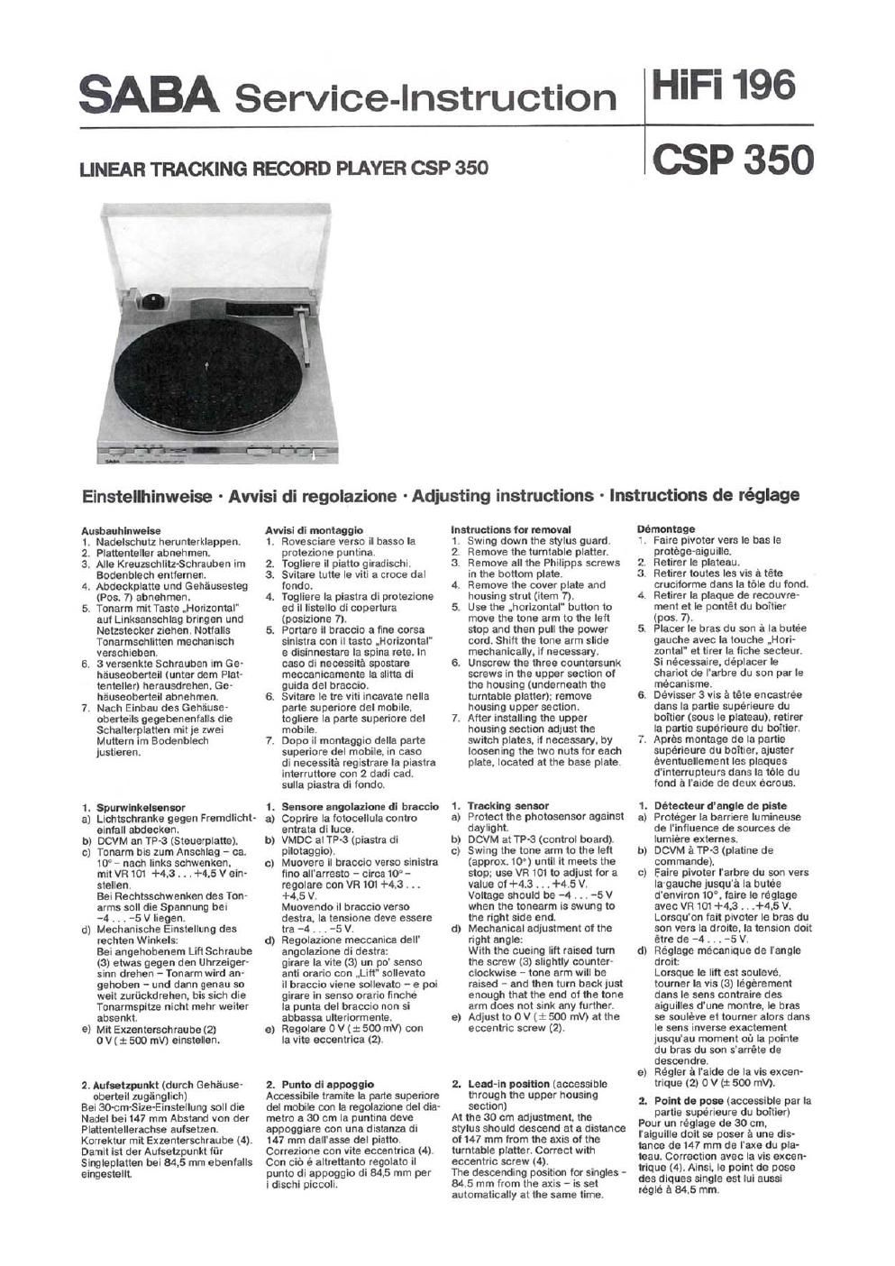
LINEAR TRACKING RECORD PLAYER CSP 350

lcsp 350

Einstellhinweise - Awisi di regolazione - Adjusting instmctlons - Instructions de réglage

Amuhlnwolu

. Nadelschutz herunterklappen.

. Plattenteller abnehmen.

. Alle Kreulschlitz-Schreuben im
Bodenhlech entiernen.

. Abdeokplstte und Gehiusesteg
(Pos. 7) abnehmen.

. Tonerm mil Taste .Horizontel'
aul Linksanschlag oringen und
Natzstecker ziehen. Notlalls
Tonermschlitten mechanisch
verschieben.

6. 3 versenkte Schreuben im Ge~
hfiuseobortell (unter dern Plat-
tenteller) herausdrehen. Ge
heuseoberteil abnehrnen.

7. Nach Einbeu des Geheuse-
oberteils gegebenanlalls die
Schelterpiatten mit 1e zwei
Muttern im Bodenblech
)ustiaren.

OIJKQN

1. Spurvrlnkoiunlor

a) Lichtschranke gegen Frerndlicht-
elnlell ebdecken.

b) DCVM an 113-3 (Steuerplalte).

c) Tonerm his zum Anschlag - ca.

10" nach links schwenken.

mit VR 101 +4.3 . . . +4.5 V cm-

slellen.

Bei Rechtsschwenken das Ton-

arms soll die Spannung bei

-4 . . . -5V liegen.

Mechenische Elnstellung des

rechten Winkels:

Bei angehobonem Lift Schrauoe

(3) etwas gegen den Uhrzeiger»

sinn drehen - ionarm wird an-

gehoben - und denn genau so

weit zuriickdrehen, bis sich die

Tonarmspltze nicht mehr waiter

ebsenkt

Mit Exzenterschrauhe (2)

O V ( :t 500 mV) einstellen.

d

6

2. Aututzpunkt (duroh Gehause-
oberteil zugingllch)
Bel 30-cm-Size-Einsleilung soll die
Nedel bei 147 mm Abstand von der
Plattentellerachse euisetzen.
Korrektur mit Exzenterschreube (4).
Demit ist der Autsatzpunkt fiir
Singleplatten mi 84.5 mm ebenialls
oingestellt

Avviti di MINOR)

1. Rovesciare verso ll basso Ie
protezione puntina.

. Togliere il pietto qiradischi.

. Svitare lutte le viti a croce dal
londo.

. Togliere la piaslre di protezione
ed il Iistello dl copertura
(posizione 7).

5. Portare il braccio afine corsa

sinistra con il taste .Horizontal'
e disinnestare Ia spine rate. In
case di necessite spostare
meocenicarnente la slitta dl
guide del brsccio.

6. Svitare le tre viti lnoevete nella
parts superiors del mobile.
togliere la parte superiore dei
mobile,

7. Dope II montaggio della parte
superiors del mobile. in case
di necessite registrars Ia piastra
interruttore con 2 dedi cad.
sulle piestra di londo.

AWN

l. Sensor- angollzlom dl tar-ode
a) Coprire Ia iotocellule contra
entrsta di luce.
b) VMDC al TP-3 (piastra di
pilotoggio).
c) Muovere il braccio verso slnistra
lino all'erresto - circa 10 -
regolare con VR 101 +4.3 . ..
+4.5 V,
Muovsndo ll hraccio verso
desire. In tensions deve essere
tre -4. . . --5V.
Regolezione meccanlca dell
angolazione dl destrm
girere la Vite (3) un po' senso
anti orario con .Lilt' sollevato
il breccio viene sollevato - e poi
girara in sense orario finche
Is punts del braccio non si
abbessa ulteriormenle.
e) Resolve 0 V ( :t: 500 mV) con
la vita eccentrics (2).

E

2. Puma dl eppogglo

Acoseeibiie trarnlte la pane superiore
del mobile con la regolezione del dia-
metro a 30 cm In puntine dove
appoggiare con una distenze di

147 mm dall'esse del piatto.
Correzione con Vite eccentrics (4).
Con cio e altrettanto regolato il
punto di appoggio dl 84.5 mm per

i dischl piccoli.

Instructions tor nmov-i

Swing down the stylus guard.

Remove Ihe turntable platter.

Remove all the Phillpps screws

in the bottom plate.

Remove the cover plate and

housing strut (item 7).

Use the .horizontal" button to

move the tone arm to the left

stop and then pull the power
cord, Shift the tone erm slide
mechanically, l1 necessary.

6. Unscrew the three countersunk
screws in the upper section 01
the housrng (underneath the
turntable platter): remove
housing upper section.

7. Alter installing the upper
housing section adjust the
switch plates. it necessary. by
loosening the two nuts tor each
plate. located at the base plate.

PS-l0."

1. Tracking sensor

3) Protect the photosensor against
daylight.

b) DCVM at TP-S (control board).

c) Swing the tone arm to the left
(approx. 10') until it meets the
stop; use VR 101 to adjust tor a
value 01 +4.3 . . .+4.5 V.
Voltage should be -4 . . . -5 V
when the tonearm is swung to
the right side end.

(1) Mechanical adjustment of the

right angle:

With the cuelng lift raised turn

the screw (3) slightly counter-

clockwise - tone arm will be

raised - and then turn back )ust

enough that the end 01 the tone

arm does not sink any further.

Adlust to 0 11(3: 500 mV) at the

eccentric screw (2).

2. Lead-in position (accessible
through the upper housing
section)

At the 30 cm ed)ustment. the

stylus should descend at a distance

oi 147 mm lrom the axis at the

turntable platter. Correct with

eccentric screw (4).

The descending position tor singles -

64.5 mm from the axis - is set

automatically at the same time.

Démontago

t. Faire pivoter vers le has le

prolége-aiguille.

Retirer Ie plateau.

. Retirer toutes les vis a téte

crucilomie dans Is this du (undo

. Retirer Ia plaque de recouvrev

merit et la pontet du ooitier
(DDS. 7)

5. Placer Ie bras du son a la bulee
gauche avec la touche .Hori-
zontel et tirer la fiche secteur.
Si necessaire. deplacer Ie
chariot de I'arbre du son par le
méounisme.

6. Devisser 3 vis a téte ancastree
dans la pertie superieure du
ooitier (sous Ie plateau). retirer
Ia psrtie superieure du twitter.

7. Apres montage de la partie
superieure du boitier. ejuster
eventuallement les plaques
d'lnlerrupteurs dans la tble du
lend a I'eide de deux ecrous.

euro

1. Détecteur dengle do piste
Proteger Ia berriere Iurnineuse
de I'intluence de soumes do
lurnlere extemes.

b) DCVM it TPv3 (plaiine de
commands).

c) Feire pivoter I'arbre du son vers
Ia gauche )usqu'it Ia outée
d'environ 10°. leire le reglage
aver: Wt 101 +4.3 , . .+4,5 V.
Lorsqu'on fail pivoter le bras on
son Vere la drolte, la tension doit
étrc de 4 . . . -5 V.

d) Réglage mécanioue de I'angle
droit:

Lorsque Ie Iltt est soulevé,
tourner la via (3) legerement
dens le sens contralre dos
aiguilles d'une montre, le bras
so souleve at toumer alors dens
Ie sens inverse exacternent
)usqu'au moment ou la polnte
du bras du son s'arréte do
descendre.

e) Healer a I'elde do la vie excen-
trique (2) O V (:t: 500 rnV).

2. Point do pose (accessible per la
parlie superieure du hoitier)

Pour un réglsge de 30 cm.

l'alguille doit se poser it une dis-

times do 147 mm de rue du ple-

teau. Correction avec la vis excen

trlque (4). Ainsi, to point de pose

des dlques single est lui aussi

régle a 84.5 mm.

Page 2

AbbJ
Illuetr.1
Fig.1
Fla

3. Lmhtihe

Bel engehobenem Litt wird mit
Schraube (1) der Abstend zwischan
Plattenteller und Abtastnaoal aul
ca. 8 mm eingestellt.

4. Nenndrehzahl (durch Boden-
platte zuganglich)

a) PitchCanflolRegler auf Mlttel-
stellung.

b) Mi! Hilte derstroboskop-Anzeige
45 Ulmin. mit VR 1 bzw. 33>:
Ulmin. miiVR 2 einstellen.

5. Weohsal do: Mlkroechatters
Balm Einbau des Mikroschalters $2
(Pas. Nr. 5!) lat daraut zu achten.
dab bei strornlosern Elekirornegnet.
d. h. bei angehobenern Liit. die
Btattkontakte geschlcssen sind.
Anderntalls slnd die .Lifl'- und
..Horizonlel"-Funktionen blockiert.

6. Wechoel den Elalttmmagneten
Mil Montageschrauben Hub aui

2 . 2.5 mm einstellentsiehe
Abb. 2).

Prlltung Poaiticmeneor
a) Tonarm in Ruheposilion.
b) DCVM an CNP 104.

Punk! 33: +5 V

Punk! 34: +5 V

Punk! 35: -4 V

Punk! 36: -4 V

Punk! 37: +3.8 V
Ptfiltlng Eloktromagnet (Lin)
Gleichstromwlderstand:
80 . . .90 Ohm.
a) DCVM zwischen 38 und 39

(CNP 105).

b) Nach DrUcken der Taste .Litt'
(Absenken): nach einem
24 Vimpuls (ca. 0.5 sec.) mus
die Spannung bei 12 V llegen und
der Eleklromagne! anziehen.

c) Nach wiederholtern Driicken
(Anhaben): 0 V.

Primng Schlittenmotor

DCVM an ON? 106, Punk! 32:
Linkslaut schnell: -10 V
Rechtslaut schnell: +10 V
Linkslaut Iangsarn: -3.5 V
Rechlslaul lengsam: +3.5 V

Auswachaeln der Abtaotnartel
Nadelelnschub nach unlen
abziehen.

Auxwecheeln on Mat-meme
Zwel Schmuben an der Unterseite
des Tonarms lose". Abtasisystem
nach vorne herausziehen - ge>
gebenantalls Zulaitungen duroh clas
Tonarrnlager nachschieben.

Dle Farben dieser Leitungen

heben tolgende Bedeutung:

WeiB - L+ linker Kanet

Blau - L- linker KanellMasse
R0! - Ft+ rechter Kanal

Griin - R- rechter Kauai/Masse

Auflweoewlcht 1.5 p

Einstelltmg mi! Tonarrnwaage.
Nach Losen darSchraube seitlich
im Balancegewicht kann dleses
verschoben werden.

3. Mezz- di aollevemento

Can .Litt' sollevato. si regola con la
me (I) la distanza tra piatto e
testina su circa 8 mm.

4. Girl nominal! (accessibili iramita
la piastra di tondo)

a) Regolatore Pitch Control su
posiziena medians.

b) Regolare osservando l'indica-
zlone stroboscopia con VR 1 su
45 girl/min. rlspettlvemente con
VR 2 an 33% girilmin.

5. SoItituzlone dei micro-
lntemnore

Ne! montaggio dei microinterrutore

Se (posizione nr. 5!) e da osservare

one i contatti siano miuei con ela!

trcmagnete senza corrente. che

vuole dire con tht soilevalo.

In case contrario la tunzlonl .Lirt" e

.Horizontai" sono bloccate.

6. Sostltuzlona dalt'elettm-

magnate
Regolare la corsa con la Viti di
montaggio su 2 . . . 2,5 mm
(vadi illustr. 2).

Controllo sensor. position.
a) Braccio In posizione di ripest).
b) VMDC su CNP l04.
: +5V
+5V
-4 V
- V
+3.8 V

Carmella elcttmllmto (Lift)

Resistanza continue- 80 . . . 90 Ohm.

a) VMDC Ira 38 e 39(CNP105).

b) Dopo la pressione del taste
.Litt' (discesa): dope un Impulse
di 24 V (ca. 0.5 sec.) Ia tensione
deve essere an 12 V e Ielettrov
magnate deve Iavorare.

0) Dope ripetuie pressioni
(sollevare): 0 V.

Controller slitt. motors
VMDC al CNP lOG. punto 32:

Curse sinistra veicce: ~10 V
Corsa destra velooe: +10 V
Corsa slnistra tents: -3.5 V
Curse destra Ianta: +3.5 V

Soltltuzione dell: puntlne
Stilare verso it based ii supporto
puntina.

Sootihlzione till Interns di
rival-manta

Allentare le due Vlti out late

inferiore del braccio. sfilara in
evanti il sistema di rivelemento -

in wso di necessita. spingere i tili
che attraversano ll cuscinetto clel
braccio.

l cclori questi till hanno il

seguente significato:

Blanca - L+ canale di sinistra

Blu - Le messe male dl sinistra
Rossc - R+ canals di deatra

Verde - R- massa canals dl desire

Peon dappooglol.5 p

Taratura con dinamomatro. ll
contropaso si sposta dopo aver
allentato la sua Vite Iateraie.

Abb. 2 Kontakta geschloseen
llluetr. 2 Contatti chiusl

Fig. 2 Contacts closed

Fig. 2 Contacts termes

3. cuelng lltt height

With the cuelng lit! raised. used
the srew (1) to adjust the clearance
between the turntable and the
stylus tor approx. 8 mm.

4. flown-l apeed (accessible
through the bottom plate)

a) Set the pitch control at its center
position.

b) Using the stroboscope as a
gauge. set for 45 RPM with VR 1
and for 33% RPM with VB 2.

5. Changlng out the mlcroowltch
When installing the 82 microswitch
(item No. 5|) insure that the leaf
contacts are closed when the
solenoid is deenerglzed. La. when
the cuaing lift is raised. Otherwise
the .Iift" and Horizontal lunctions
will be blocked.

6. Changing out the solenoid

Use the mounting screws to set the
stroke length at 2 to 2.5 mm

(see fig. 2).

Checking position sensor
3) Tone arm in its rest position
b) DCVM at CNP 104.

Test point 33: +5 V
Test point 34: +5 V
Test point 35: -4 V
Test point 36; -4 V
Test point 37: +3.3 V

ducking solenoid (cu-Ins Iltt)

DC resistance: 80 to 90 Ohms.

a) DCVM between 38 and 39
(CNP 105).

b) After depressing the 'llft" button
(lowering):
Following a 24 V pulse (approx.
0.5 sec.) the voltage must be at
12 V, pulling up the selenoid.

c) Alter pressing again (raise): 0 V.

Checking the lilde motor

DCVM at CNP 106, test point 32:
Rapid traversing to the lett: -10 V
Rapid traversing to the right: +10 V
Slow traversing to the left: - 3.5 V
Slow traversing to the right: +3.5 V

changing out the ctylue
Pull the stylus Insert downwards.

Charging out thecartrldoe
Loosen the two screws on the
underside ot the tone arm: pull out
cartridge towards the (rent. I! may
be necessary to push the
connecting leads through the
tonearm bearing to provide
sutficient stack.

The colours at these wires have
the lollowing meanings:

White - L+ left channel

Blue - L- let! channel/ground
Red - R+ right channel

Green - R- right channel/ground

Tracking lore. 1.5 p

Adjustment with tonearm balance.
The counterweight can be moved
alter loosening the lateral screw.

3. "auteur du lift

Lorsque Ie lltt est soulevé. regler
avec la vis (1) l'écart entre lo pla-
teau at l'eiguille da lecture a 5 mm
BHV.

4. Hombre nominal do toun
(accessible par la plaque de lend)

a) Régleur Pitch Control en position
mediene.

b) Régler é I'eide do l'attiehage du
strooosoope estavacVRtet
33 is t evec VR 2.

5. Eatenge du mlcrotupteur

Lors du montage du micrompteur 52
(pos. 5t). veillor a co que les contacts
a lames soiem farmer: lorsque
I'électrrralmant n'est pas sous ten-
sion. cest-a-dire lorsque la lit! est
soulevé. Sinon. les tonctlons 'litt'

et 'horizontal" sent bloquées.

6. Echanga rte Idloctro-drnant
Raglar la levee a 2 . . . 2.5 mm avec
les vis de montage (volr fig. 2).

Cont! du detecteur do position
a) Arbre du son en position de repos.
b) DCVM a CNP t04.

Point 33: +5 V

Point 34: +5 V

Point 35: -4 V

Point 36: -4 V

Point 37: +3.8 V
(2mm do l'électroalment (lift)
Resistance courenl continu:
BO . . . 90 ohms.

a) DCVM entre 38 at 39 (CNP 105)i

b) Apres avoir appuye sur la touche
.lift' (abaisse): apres une imputation
de 24 V (0.5 sec. ean, In ten-
sion doit etra de 12 V at t'électro-
alman! doit étra attire.

c) Aprés des pressions repetées
(levee): W.

Comte du mm on chariot
DCVM é ON? 106. point 32:
Marche a gauche rapida- ~10 V

Marche 'a droite rapids: +10 V
Marche a gauche Iente: - 3.5 V
Marohe a droite Iente: +3.5 V

Echengo do l'algullle do lecture
Retirer vars Ie be: Is tlroir da
Iaiguille.

Eon-nae au system. do lecture
Devlseer deux v13 sur la cote in-
ferieur du bros du son. lirar vars
lavant Ie systema de lecture en
taiaant avancar eventuallamant

les cables in trevers Ie palier de
larbre du son.

Le code de couleur des cables
ci-apres:

Blenc - L+ canal de gauche

Biau - L- canal do gauchelmasse
Rouge - R+ canal de droile

Verl - R- canal de droitelmasse

Fons- dlppul 1.5 p

Raglage a I'aide d'une balance as
bras do lecture. Le contra polds
peut etre deplacé apres evoir
devissé la vie de blocage laterals.