Saba breisgau 12 service manual

This is the 4 pages manual for saba breisgau 12 service manual.
Read or download the pdf for free. If you want to contribute, please mail your pdfs to info@audioservicemanuals.com.

Page: 1 / 4
left right
saba breisgau 12 service manual

Extracted text from saba breisgau 12 service manual (Ocr-read)


Page 2

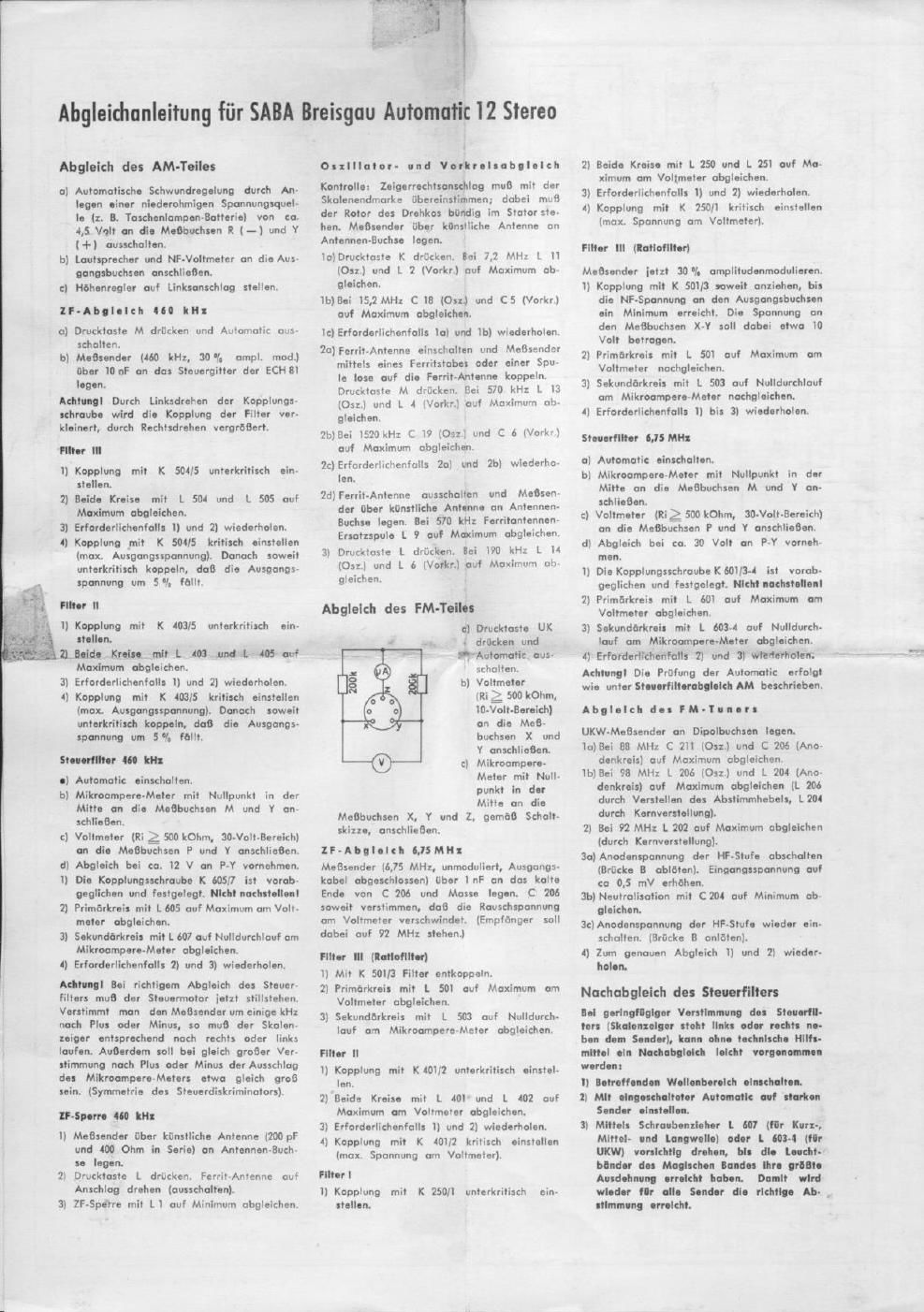
Alignment Instructions for SABA Breisguu Automatic i2 Stereo

AM Alignment

a) Eliminate AVC by applying mm 5 volts
from a low-resistance battery to test
points it (-) and V l+).

b) Connect loudspeaker and output-meter to
the output terminals.

c) Turn treble control to left stop.

OI: ll Align-ant

a) Press key M and switch off Automatic

b) Connect a signal generator (60 kc, 30%
ampl. mod.) through a 0.0) mi. capacitor
to tho contral grid at the mixer tube
ECH ll.

Attootlonl The coupling at the IF transformer:

decreases by turning the screw counter-clock-

wiso and increases by turning clockwise.

ll Transfer-er It

1) Adiust coupling subcritical with X 50415.

1) Adiutt bath circuits with L 504 and L 505
to max.

3) if necessary repeat l) and Z).

4) Adlust coupling critical with K 501/5 (max.
output). Then couple soberitical until the
voltage drops by 5']..

l Transfer-or II

l) Adiust coupling subcritical with K 403/5.

7) Adiust both circuits with L 403 and L405
to max.

:t) If necessary repeat I) and 2).

l) Adiuot coupling critical with K 403l§ (max.
output). Then couple subcritical until the
voltage drops by 5%.

Central lremterntor I I:

a) Switch on Automatic.

a) Connect zero-centre microammotor to tost
points M and Y.

c) Connect DC voltmeter (ages rnegohm.
3 volts full scale reading) to test paints
F on! V.

d) Untortolre the alignment at about I1 volts
between P and V.

I) The coupling screw K 605 is pro-aligned
and set. Do not ad|ostl

1) Adiust primary circuit with L 605 to max.
at valtmotor.

J) Adiust secondary circuit with L 607 to
xoro at microan-lmeter.

4) If necessary repeat 1) and 3).

Aflelfllnl If the control transformer is prop-

erly aligned. the control motor must stand

still. it now the signal generator is detunod

a few kc plus or minus. tho pointer must

run to the right or left. Besides the scale

reading of tho microarnrnotor should be same

but opposite it tho downing has the same

amount to each side.

1 tree I he

1) Connect signal generator through dummy
antenna (200 mini. and 400 ohms in series)
to antenna socket.

2) Press key L. Switch off ferrite antenna
(turn to left or right stop).

I) Adiust IF trap with L i to min.

Alignment ot Oecliloter

and P selection

Check: with pointer step on right, painter

must be at corresponding point on the dial.

The rotor at the variable capacitor must tit

llush in the stator.

Connect signal generator through dummy an-

tanna ta antenna socket.

ia)i're5| key K. At 7.2 M: adiust L ll lasc.)
and L 2 lent.) to man.

lb)At i5.2 Mc adios! C I! (asc) and C 5
(ant) to max.

ic)lt necessary repeat la) and lb).

to) Switch on ferrite antenna. Couple signal
generator loosely to ferrite antenna by
means of a ferrite rod or a coil.

Press key M. At 570 kc adiust L I] last.)
and L 1 (ant) to max.

2b)At i520 kc adjust C )9 lost) and C .5
lent.) to max.

2cm necessary repeat 2c) and 25).

2) Switch off ferrite antenna. Connect signal
generator through dummy antenna to am
tenna socket. At 570 kc adjust L9to max.

3) Press key I. At 190 kc adjust I. litotc)
and L 6 taut.) to max.

FM Alignment

a) Press key UK
and switch 0"
Automatic.
Connect a volt-
meter (Ri g 0.5
mogohm,
)0 volts full
scale reading)
to test points
X and Y.
c) Connect xero-

centre

is

mlcroammctar to text points x, v and z.

If Allgo-ont (.1! Mc

Connect signal genorator (5]5 Me, unmodu-
iated, autput cable matched) through 1000
Mini. to low side at C 206 and chassis.

Dctune c 206 until the noise voltage ding.
pears at the valtmctar (for this set receiver
to 92 Mc).

I! Im-Iterator ill (latte-Detector)

i) Adiust coupling subcriticai with K Sol/3.

2) Adiust primary circuit with L 501 to max
at voltmeter.

s) Adiult secondary circuit with L 503 to
core at micraammotar.

Il-Iroestoraier I
1)Adiust coupling subcriticol with K will.

2) Adiust both circuits with L 40) and L 402
to mill. at voltmeter.

3) It necessary repeat 1) and 2).

4) Adiult coupling critical with K 40]! (max.
at voltmeter).

l! Transformer I

l) Adiust coupling subcritical

with K 250". N
1) Adiust both circuits with kg?
L 250 and L 251 to melt. g :3;
at voltmeter. a La,
3) If nnccssaryiupcutilandm gwg
l) Adlust coupling critical _, ,
with K zso/l (max. " l
at voltmeter). I
ll Transformer ill
[Ratio-Detector)

Signal generator must now

bo 30']. ampi. mod.

l) Tighten coupling with K
Sill/3 until the audio volt-
age at the output reaches

2) Correct adlustrnont at primary circuit with
L Sol to max. at voltmeter.

3) Correct odiustment at secondary circuit
with L 503 to zero at mlcroomrnoter.

4) it necessary repeat I) to 3).

Control Treader-or 6.75M:

a) Switch on Automatic.

h) Cannoct xoro points M and Y.

c) Connect voltmeter (ages megahrn, so
volts full scale reading) to test point: P
and V.

d) Align at about I volts at PvV.

l) The coupling screw KaolIS-Als preaiigned
and set. Do not adiestl

2) Adiust primary circuit with L 601 to max.
at voltmeter.

3) Adiust secondary circuit with L 603 to
xera at microammotor.

I) If necessary repeat 1) to 3).

Attontloai For checking the automatic see

alignment of cootrol trout-noos- us he.

Allgo ent ot the FM to

Connect VHF signal generator to dipole

sockets.

ia)At as M: adiust C 211 lose.) and C 206
(rt) to max.

ibiAt 93 Mc adiust L 206 talc.) and L 20
(r. t.) to max. (L206 by shitting the tuning
rod, L 20 by shifting the care).

2) At 92 Mt: adiust L 202 to max. (by shitting
the care).

3a)Cut a" plate voltage at r. t. anpl. (urt-
solder connection 3).
increase Input voltage to about 05 millir
volt.

3blAdiust neutralizing with c 204 ta tnin.

kilo-solder connection I.

4) For ouact alignment repeat I) and 2).

lie-Alignment of Control Transformer

It the control trust-nor bee-o My

dew-ed [pol-nor to the left or right at

natloo), tho trade-or NI polity Do
realigned wtthoet ooy tech-loot pelt

I) Svrltcl ea carom-dog m range.

1) tone te a stroog notion with Automatic
oo.

3) Tie a screw Moor and turn carotelty
I. m (tor short, reaction and long wave)
or I. m: (tor FM) until pointer ls exactly
on station loholoo by magic eye).

LMIIIMM
on"

its min. The voltage bot-
woan toot points X and V

should be about it) valts.