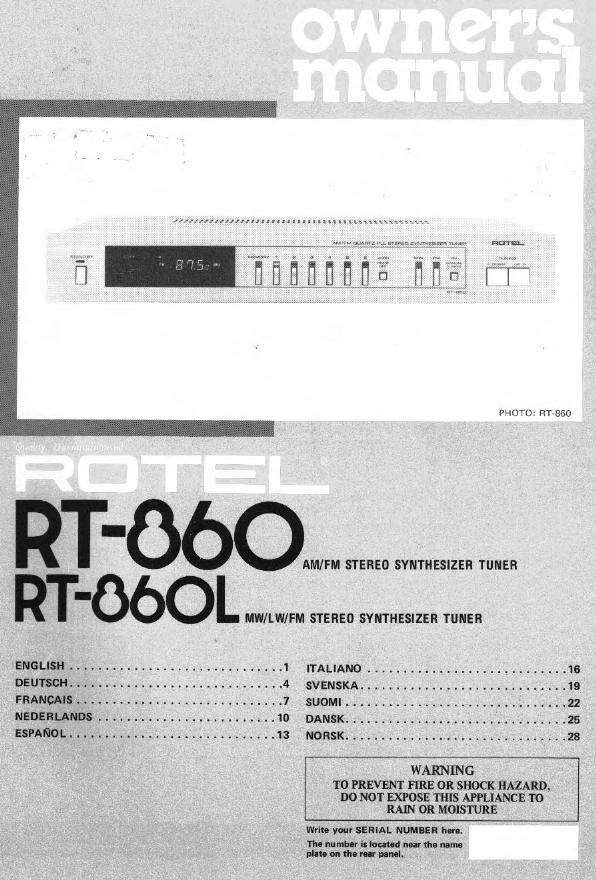
Rotel RT 860 860L OM

This is the 4 pages manual for Rotel RT 860 860L OM.
Read or download the pdf for free. If you want to contribute, please mail your pdfs to info@audioservicemanuals.com.

Page: 1 / 4
left right
Rotel RT 860 860L OM

Extracted text from Rotel RT 860 860L OM (Ocr-read)


Page 2

[lililltiil

AM/FM STEREO SYNTHESIZER TUNER RT-86O
MW/LW/FM STEREO SVNTHESIZER TUNER RT>860L

CAUTION

At long as the power cord is plugged into an
AC outlet. power is aupplied to the unit
regardleet or the setting ol the Standby
Button,

INTRODUCTION

We at Hotel want to thank you lor purchasing
our audio product.

Rotal audio products are designed to use the
latest electronic technology. and they incorpo-
rate our long experience as a specialist manulec-
turer 0! audio equipment. We are oonlident
met you w-ll find HIirleclIon in the high
quality sound and top pet'lorlnanco. and that
you will llnd pleasure in the Iunct-onll beauty
achieved through human-engineering concept.
Belove starting operation. pleaaa read this
instruction manual thoroughly and acquaint
yourself with the proper mode ol uting the unit
and all tlt connections.

We hope you will enjoy toonotch performance
tor many years to come.

INSTALLATION

Be sure to place the unit in a level and llat place
where it is lree Irom humidity. vibration. hlgh
mmperlluro and not llptned to direct sunliml.
Be carehtl not to plan the unit in a highly
enclosed place such as near a wall or on a
bookthall. A poor ventilation will ceuee unfi-
eireble eltects to the unit.

POWER SUPPLY CONNECTION

For power the unit requlret the normal hottta
electrical current (AC). Vou may simply plug
the unit into a wall outlet, or into the AC out-
let on the Hotel Remote Control Center RR-
NO.

Note that Mien you plug the power cord into a
swnched outlet on amplit r. the stored memo
ry will be lost three days my switching oil the
emplilier.

CAUTION: Do not apply power lM'lhoul lirst
making sure the proper connection: are com-
pleted, II you live in UK, and your unit comes
with Z-core card without e plug. be sure to read
the exclueive cautlon (or UK.

EXCLUSIVE NOTE FOR u

It your unit cornea with a 2-core cable
without a plug. melt. certain live and
neutral leads are connected to the proper
terminals. Check that the terminals are
screwed down firmly and no loo. strand:
of wire are preurlt.

IMPORTANT: Th. wires in_lhi: meins land
are coloured in accordance with the lunar»-

i

NEUTRAL
BROWN: LIVE
As the colour: of the wires in the mains lead
at thit apparatut may not correepond with .
the coloured markings identilying the
terminal: in your alley proceed at follows.
The wire which it colour, BLUE mun be
connected to the terminal which it marked
with the letter N or coloured BLUE or
BLACK. The wire which is coloured '
BROWN must be connected to the terminal
which is merited with the letter L or colour-
ed BROWN or RED.

CONNECTION WITH INTEGRATED
AMP OR PREAMP

Usinu RCA pin cordt, securely connect the
OUTPUT terminals on the rear panel of the
unit to the TUNER (or AUX) terminals ol
amplifier. Malta absolutely sure that RIGHT
terminal at one uni is connected to the RIGHT
terminal or the other. and LEFT to LEFT.

AMPLIFIER

ANTENNA INSTALLATION AND
CONNECTION

a FM Antenna

Proper lnnallaticn or antenna it the key to
tmooth clonal reception. To inaull the attached
T-shape indoor antenna. atratch it [out and
acute horizontally along a wall or the like
in a location where signal reception it optimal.
Securely connect the antenna to FM antenna
nrminals merited "3009" on the rear panel.
If outdoor type FM antenna is rnilsllod. the
T~shape antenna it not neceeeary. For proper
use or your outdoor FM antenna. lollow the
tnttructione below.

1. Be sure to select the most appropriate
type at antenna lor the clonal reception condlr
tions in your area.

2. A 750nm coaxial cable is recommended
in connecting the antenna to the unit.

3. Set the antenna in a position as high at

RIm

possible
obstructions nearby allect reception.

tl buildings. mountains or other

4. The 750hm coaxial antenna cable
thould be properly hooked up to the designated
antenna terminal: on the rear panel: Locate the
terminate labeled 75D". Connect the center
conductor ol the cable to the leIlAhand ter-
minel. and connect the outer braided conductor
ol the cable to the right-hend terminal (marked
"GND").

RTML. UK model only

FM GND AM

FM GNO AM