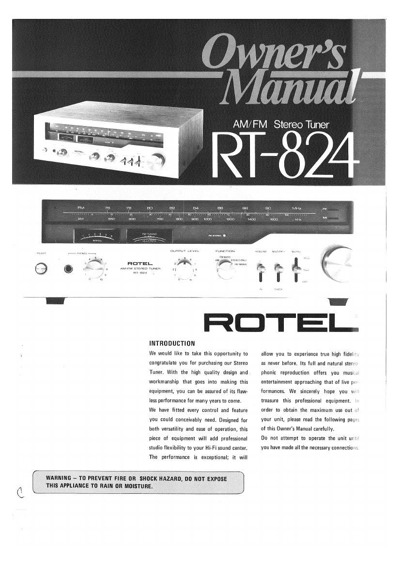
Rotel RT 824 OM

This is the 3 pages manual for Rotel RT 824 OM.
Read or download the pdf for free. If you want to contribute, please mail your pdfs to info@audioservicemanuals.com.

Page: 1 / 3
left right
Rotel RT 824 OM

Extracted text from Rotel RT 824 OM (Ocr-read)


Page 1

AM/ FM Stereo

RT-824

m n mm H. mm .

m r v We \

UuTDur Ltvkl.

FtINETlUN
HOTEL

FMAuw
w W mm»
, nu mm
AM/FM swam rwm .. . .4 s
. y , .
my -aer I V
- , y u -.
u m o- in ~ '

RDTEI-

INTRODUCTION

We would like to take this opportunity to
congratulate you for purchasing our Stereo
Tuner. With the high quality design and
workmanship that goes into making this
equipment, you can be assured of its flaw-
less performance for many years to come.
We have fitted every control and feature
you could conceivably need. Designed for
both versatility and ease of operation, this
piece of equipment will add professional
studio flexibility to your Hi-Fi sound center.
The performance is exceptional; it will

WARNING - TO PREVENT FIRE OR SHOCK HAZARD, DO NOT EXPDSE
THIS APPLIANCE TO RAIN DR MOISTURE.

allow you to experience true high fidelm
as never before. Its full and natural stereo
phonic reproduction offers you muSl'LUl
entertainment approaching that of live per
formances. We sincerely hope you wrl
treasure this professional equipment in
order to obtain the maximum use out ui
your unit, please read the following page.
of this Owner's Manual carefully.

Do not attempt to operate the unit until

you have made all the necessary connections.

Page 2

OUTDOOR AM

FM-4 CHANNEL

DETECTOR OUTPUT

(Lise to accept an adapter to
enable receive 4-channel broads
casting whenever ellocted in the
iuturel

AM FERRITE
BAR ANTENNA-r

STEREO
INTEGRATED
AMPLIFIER

STEREO INTEB

ll rr'rr- INDOOR FM ANTENNA SOD

ANTENNA

AC OUTLJT.
UNSWITCHED
(MAX 150W)

RATED AMPLIFIER

UUTDDDR FM ANTENNA 3mm

AC FUSE

REAR PANEL CONNECTIONS

75$! COAXIAL ANTENNA
ADAPTER SOCKET

AC POWER CDRD

INSTALLATION

lMPOfiTANT: he not apply power to this
umt without iirsT niakrng sure That all The
necessary connections are properly made,

AM ANTENNA CONNECTION

Nu external antenna will generally be re
nuired lor AM, since a lernte leepstick
antenna is suppllEd at the rear of the unit
For hast possihle reception, extend the
luuostick lullv away lrolrl the tuner chassis

ll you live In a dlflicult reception area, the
use at an external or outdoor antcnna may
be desirable Connect a single Wire antenna
lead to the terminal marked AM on the
rear chassis, The wire antenna should he as
long as possihle, and oriented lor best re»
caption. it must be kept away irorn large
metal objects, power lines or electrical
rnachinery To insure reception wlthuut ex-
traneous noise.

FM ANTENNA cunnEchuN

Uwrng to the high sensitivity or the FM
tuner section of The unit, the antenna wlre
supplied is Sulllclent ior most locations
connect This to hoth FM antenna Terrninals
marked 300 ohms, and mount horizontally,
lor instance by tacking To the shclr on
which the receiver is mounted, in dirlicult
reception areas, the use at an outdoor
antenna may prove necessary. Follow lts
instructions ior proper connection

Wllerl usmg a 75rohm unbalanced coaxtal
cahle for antenna, you may connect he.
Tween 75-ohm and 6 Terminal posts with
the outer conductor or shield all the cable
connected to the 5 terminal or use an
adapter holder and plug into the 75:1
adapter socket Follow Instruction on
coaxial cable on further details.

GROUND

Although it is not necessary to do so, but It
you wish to ground The Tuner, connect a
wire lrorn the terminal designated GND on
the rear chassis to The ground Ierntlrlal on
your amplilier or to a nail driven into the
earth

vARlAeLElnuipur Level Control)

AND NDN-VARIAELE OUTPUTS

There are two pairs o~ output jacks designat-
ed LEFT and RIGHT on the rear chassis.
The Iert hand pair IS a standard, non-
varlable output lur use with most standard
anipliners. These pair or output should he
connected To The corresponding iart and
light Input (TUNER or AUXI lacks on
your anrpiilier. For your convenience, The
connecting cahles to» this purpose are supr
filled with this unit

The ngtrt hand pair l: a variahie output of
which output level can be varied lrom U to
0.3V l3lJ%, AODHZI lor AM and lroni O to
1.5V (100%, AOIIHZ) lor FM with the out

put level control on the front panel. This
output is lor use with amplillels whose
tnput level requirements are dlllerent from
the standard amplifiers. The Control as Its
lelt most position is U output. Turning it to
the right will increase the output level
propurtlunalely, and at its light must post-
thin, The output level will he at maxtnruni.
To achieve appropriate output level lor
your amplifier's trlput requirement, set the
control to the position where The sound
lIun'l the speakers is equally loud as when a
record pluyEl is played through your
amplltter lwtth The volume setting set at
the same level).

AC POWER INPUT CORD

Vour tuner has heen specially designed so
that It may he connected to a variety at
power sources. You may connect The AC
Power Input Cord directly to a wall plug,
in which case the power will he supplied To
The Tuner independent or your arnplilier. Or,
you may connect it To your amplifiers
switched or unswltched AC outlet II it is
connected to a switched outlet, hy leaving
the power button ol the tuner on, you will
he ahle to maintain svnTchrng control tor the
Tuner with your arnplilier. no is connected
To an unsvvttched outlet, like connecting To
a wall outlet you must use the tuners own
power button for switching control.

VOLTAEE SELECTION

(not available for U.K. and Scandynavlal
The Tuner is a variable voltage equipment
that can run on IDOV, ll7V, ZZflV or 240V
power supply. Your unit cornes already
preset at the proper voltage tor use in your
area; however, it you move To an area where
the power supply voltage is drrierent, the
voltage setting can be manually changed.
BE sues THAT YOUR UNIT is NOT
CONNECTED TO THE POWER SOURCE
BEFORE ATTEMPTING TO MAKE THIS
CHANGE.

To change the voltage setting, remove the
name plate on the rear panel and locate the
VOLTAGE SELECTOR lsee figure below),

FRONT PANEL
CONTROLS

o TUNING KNOB: heavy itywheci actlDrI
allows easy and precise Tuning on both AM
and FM staTions,

onunuo swtrcil: activates a circuit
which reduces audible TntersTaTion noise
when tuntng from station to station In
FM at tvm muting threshold level steps ,
1an or souv. Since very weak signals may
he muted at The same time] leave the control
at Orr position when you with To pick up
very weak stations.

asauxce SELEOTOR cONTiiuL:
enahles you to select The program you
desire rroni AM, FM STEREO, STEREO
ONLY (FM) and FM MONO.

0 HI BLEND SWITCH: allows you to
reduce annoying noise mixed In with signal.
This switch, however, should not be always
tell 'ot OFF position unless It Is necessary,

9 PDWER swn'cu: supplies power to The
tuner and in any component connected to
The switched AC outlet on The rear chassis,
When the switch is ON, dial scale and
nrete'rs wtll be illuminated.

9 HEADPHONES VOLUME LEVEL CON-
TROL: allows you to regulate the sound
level led into your headphone connected to
this unit's HEADPHDNE RECEPTABLE.
Rotate clockwise for increase In volume
level.

OPERATION

Having made all connections according to
The preceding instructions and become
ianriliar with The runctions oi the unit, you
are ready to operate The eguipnrent. Apply
power hy plugging into the power source
and pushing in The PUWER hutton.

Pull up The Voltage Selector plug which has
a white arrow on its top. Reinsert the plug
in the Selector Ease so that the head at the
arrow lines up with the pointer line of the
voltage you desire.

cONNEOTluc Tn enwen sumv
For power the unit requires The normal
house elecTricaI current IAC). Simply plug
the unit to a wall outlet

II in any doubt about connecting to the
power source,cunsu|t a qualified electrician.

commit, no not apply pawar to the
equipment without first making sure rheT
speakers are connected properly and that
the unit's VOLUME control is set to mini-
mum. it you live in U.I<. and your unit
comes with s-corc card without a plug, he
sure to read the iollewing note.

a NEAOPHONES RECEPTACLE: sunply
plug in your headphone lead tor private
listening. you may rurn on speakers Try
using controls on your ampllller ir wish To
listen to headphone only.

EMULTIPATH SWITCH: allows you to
reduce FM interference noise caused by
multipatll characteristic. Flip the switch
ON and relocate you FM antenna (usually
T'-shapc dipole antenna) until The pointer
ul multipath meter lbuiltrin with FM tuning
meter) deliects least and approaches the
center, Be Sure to leave the switch OFF
when not In use.

0 FUNCTION INDICATOR LIGHT:
vtsually indicates the selected program FM
or AM.

(0512le INDICATOR LlcllT: auto
rnatically lights up on the dial glass to visual-
ly indicate whenever an FM stereo broad
E351 IS tuned,

PRELIMINARY CHECK: it the dial scale
has lulled Illuminate, remove and check the
Al: ruse. ii the fuse is irluwn, check possible
reasons lor the hlowout leg. defective AC
power cord etc.) and replace with same
rating ruse.

m SIGNAL STRENETH TUNING METER:
shows the level oi the incoming signal.
When used In the AM pusitionl tune for
maximum dellection to the right lor best
possible reception. When Used In the FM
position, also tune for maximum Indication
but operate in conjunction with the FM
tuning meter.

03 FM TUNING METER: designed to
operate on a null or zero" center principal.
Time for The dead center position lor hest
possipie reception and minimum distortion.
it is also used as the multipath meter in
conjunction with the nruitipaTh switch.

(D OUTPUT LEVEL cONTnuL: see
"VARIABLE ANIJ NDNVVARIABLE OUT»
PUTS section lor operation

necElvtNo FM Alto AM anuAncASTs
1. FM STEREO

Under normal use for all FM hroadcasts The
Tunction selector control should he placed
in The PM STEREO positto TIlls Tuner is
equipped with a stereo sensing circuit which