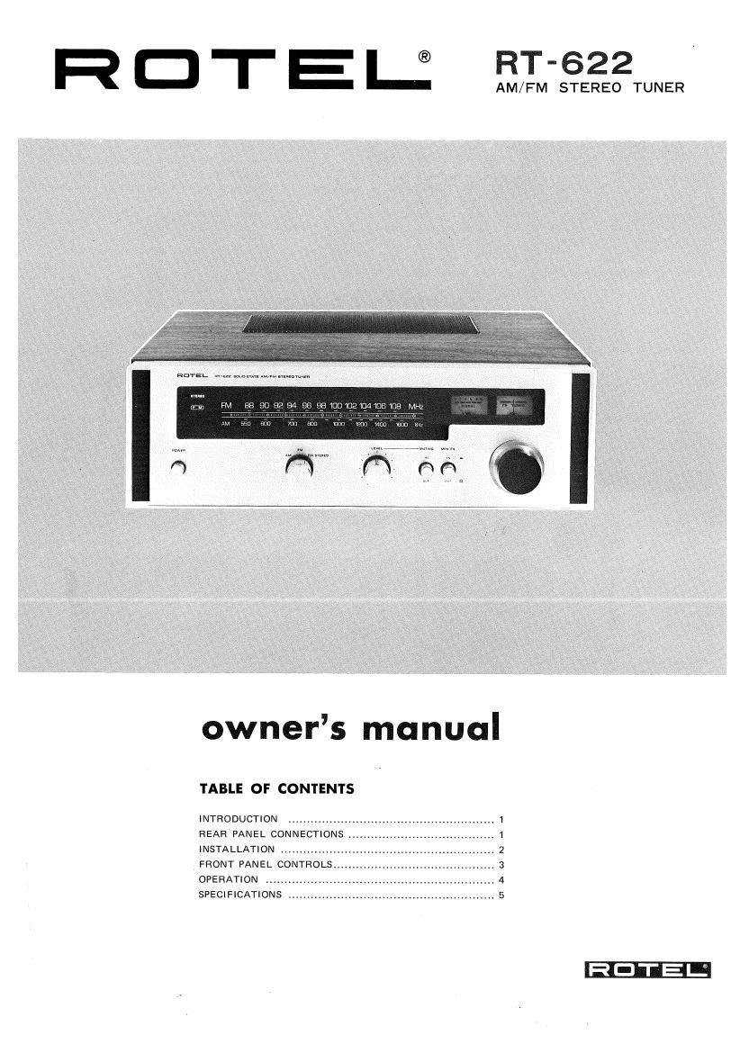
Rotel RT 622 OM

This is the 5 pages manual for Rotel RT 622 OM.
Read or download the pdf for free. If you want to contribute, please mail your pdfs to info@audioservicemanuals.com.

Page: 1 / 5
left right
Rotel RT 622 OM

Extracted text from Rotel RT 622 OM (Ocr-read)


Page 1

R C) '1" E |_® 522

rm m:

owners manual

TABLE OF CONTENTS

INTRODUCTION ..................................................... I
REAR PANEL CONNECTIONS ....................................... 1
INSTALLATION ..............
FRONT PANEL CONTROLS
OPERATION ..................
SPECIFICATIONS

Page 2

INTRODUCTION

We would like to take this opportunity to thank you for
purchasing our Stereo Tuner. With the high quality design
and workmanship that goes into making this equipment,
you can be assured of its flawless performance for many
years to come.

We have fitted every control and feature you could
conceivably need. Designed for both versatility and ease
of operation, this piece of equipment will add professional
studio flexibility to your Hi-Fi sound center. The
performance is exceptional; it will allow you to

experience true high fidelity as never before. Its fUII and
natural stereophonic reproduction offers you musical
entertainment approaching that of live performances. We
sincerely hope you will treasure this professional
equipment. In order to obtain the maximum use out of
your unit, please read the following pages of this Owner's
Manual carefully.

Do not attempt to operate the unit until you have made
all the necessary connections.

REAR PANEL CONNECTIONS

759 COAXIAL
ANTENNA
HOLDING BRACKET

OUTDOOR
FM ANTENNA
3009

OUTDOOR
AM ANTENNA

AM FERRITE BAR ANTENNA

own» . m was:
anncmtmn ma JSE

.. ,F :i~
QQQQ UGO

AC POWER CORD
AC OUTLET, UNSWITCHED

(MAX 200W)
AC FUSE
VARIABLE OUTPUT 1A, 100_120V
I:I\|IV|D(A%:ENNA - LEVEL CONTROL 0.5A, 220-240V
30052 "

%

GROUND

INPUT INPUT

STEREO PRE-MAIN

STEREO PRE-MAIN
AMPLIFIER AMPLIFIER

INSTALLATION

IMPORTANT: Do not apply power to this unit without
first making sure that all the necessary connections are
properly made.

AM ANTENNA CONNECTION

No external antenna will generally be required for AM,
since a ferrite loopstick antenna is supplied at the rear of
the unit. For best possible reception, extend the loopstick
fully away from the tuner chassis.

If you live in a difficult reception area, the use of an
external or outdoor antenna may be desirable. Connect a
single wire antenna lead to the terminal marked AM on
the rear chassis. The wire antenna should be as long as
possible, and oriented for best reception. It must be kept
away from large metal objects, power lines or electrical
machinery to insure reception without extraneous noise.

FM ANTENNA CONNECTION

Owing to the high sensitivity of the FM tuner section of
the unit, the antenna wire supplied is sufficient for most
locations. Connect this to both FM antenna terminals
marked 300 ohms, and mount horizontally, for instance
by tacking to the shelf on which the receiver is mounted.
In difficult reception areas, the use of an outdoor antenna
may prove necessary. Follow its instructions for proper
connection.

When using a 75-ohm unbalanced coaxial cable for
antenna, connect between 75-ohm and G terminal posts
with the outer conductor or shield of the cable connected
to the G terminal after fixing the cable through the
holding bracket.

GROUND

Although it is not necessary to do so, but if you wish to
ground the tuner, connect a wire from the terminal
designated GND on the rear chassis to the ground terminal
on your amplifier or to a nail driven into the earth.

VARIABLE AND NON-VARIABLE OUTPUTS

There are two pairs of output jacks designated LE FT and
RIGHT on the rear chassis. The left hand pair is a
standard, non amplifiers. These pair of output should be connected to
the corresponding left and right input (TUNER or AUX)
jacks on your amplifier. For your convenience, the
connecting cables for this purpose are supplied with this
unit.

The right hand pair is a variable output of which output
level can be varied from 0 to 0.3V (30%, 400Hz) for AM
and from 0 to 1.5V (100%, 400Hz) for FM with the knob

marked VARIABLE on the right hand side. This output is
for use with amplifiers whose input level requirements are
different from the standard amplifiers. The VARIABLE
knob at its left most position is 0 output. Turning it to
the right will increase the output level proportionately,
and at its right most positon, the output level will be at
maximum (same level as that for standard output).

To achieve appropriate output level for your amplifiers
input requirement, set the VARIABLE knob to the
position where the sound from the speakers is equally
loud as when a record player is played through your
amplifier (with the volume setting set at the same level).

AC POWER INPUT CORD

Your tuner has been specially designed so that it may be
connected to a variety of power sources. You may
connect the AC Power Input Cord directly to a wall plug,
in which case the power will be supplied to the tuner
independent of your amplifier. Or, you may connect it to
your amplifier's switched or unswitched AC outlet. If it is
connected to a switched outlet, by leaving the Power
button of the tuner on, you will be able to maintain
switching control for the tuner with your amplifier. If it is
connected to an unswitched outlet, like connecting to a
wall outlet you must use the tuners own power button
for switching control.

VOLTAGE SELECTION

The tuner is a variable voltage equipment that can run on
100V, 117V, 220V or 240V power supply. Your unit
comes already preset at the proper voltage for use in your
area; however, if you move to an area where the power
supply voltage is different, the voltage setting can be
manually changed. BE SURE THAT YOUR UNIT IS NOT
CONNECTED TO THE POWER SOURCE BEFORE
ATTEMPTING TO MAKE THIS CHANGE,

To change the voltage setting, remove the cabinet and
locate the VOLTAGE SELECTOR (see figure below). Pull
up the Voltage Selector plug which has a white arrow on
its top. Reinsert the plug to the Selector Base so that the
head of the arrow lines up with the pointer line of the
voltage you desire.