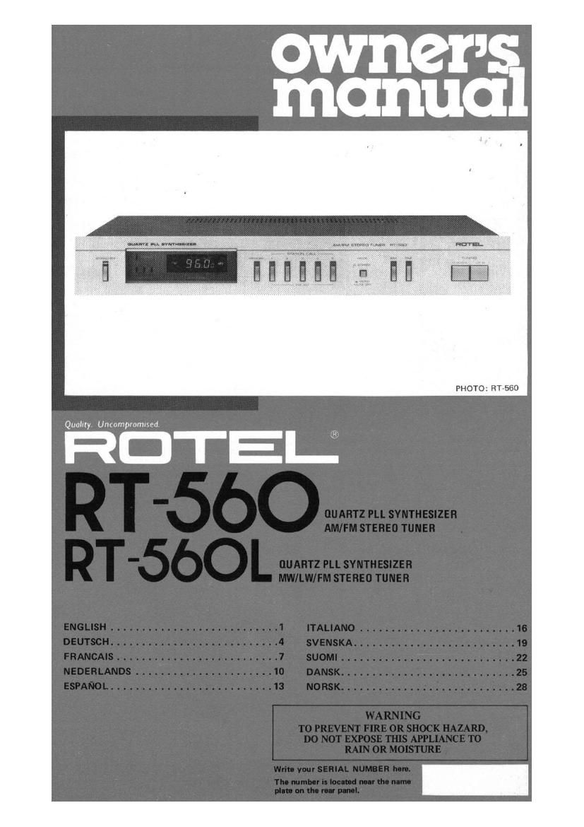
Rotel RT 560 Owners Manual

This is the 4 pages manual for Rotel RT 560 Owners Manual.
Read or download the pdf for free. If you want to contribute, please mail your pdfs to info@audioservicemanuals.com.

Page: 1 / 4
left right
Rotel RT 560 Owners Manual

Extracted text from Rotel RT 560 Owners Manual (Ocr-read)


Page 2

IIIIilISII

AM/FM STEREO SYNTHESIZER TUNER RT-560
MW/LW/FM STEREO SYNTHESIZER TUNER RT-SGOL

INTRODUCTION

We at Hotel want to thank you for purchasing
our audio product.

Rotel audio products are deeiwted to use the
latest elecmnic technology, and they incorpo-
rate our long experience I a specialist menulae-
turer oi audio equipment. We are confident
that you will find satisfaction in the high
quality sound and top perlormancn, and that
you will find pleasure in the functional beauty
achieved through human-engineering concept.
Belore startlng operation, please read thix
instruction manual thorouwly and acquaint
yourself with the proper mode oi using the unit
and all its connections.

We hope you will enjoy top-notch performance
for many years to come.

INSTALLATION

Be sure to place the unit in a level and flat place
where it is tree from humidity, vibration, him
temperature and not exposed to direct sunlight.
Be careful not to place the unit in a himly
enclosed place such as near a wall or on a
bookshelf. A poor ventilation will cause unde-
sirable effects to the unit.

POWER SUPPLY CONNECTION

For power the unit requires the normal house
electrical current (AC). You may simply plug
the unit into a wall outlet, or into your ampli-
fier's unswitched AC outlet.

Note that when you plug the power cord into a
switched outlet on amplifier, the stored memo-
ry will be lost three days after switching oil the
amplifier.

CAUTION: Do not apply power without first
making sure the proper connections are com
plated. ll you live in U.K. and your unit comes
with 2core cord without a plug, be sure to read
the exclusive caution lor U.K.

EXCLUSIVE NOTE FOR U.K.

If your unit comes with a 2-core cwle
without a plug. make certain live and
neutral leads are connected to the proper
terminals, Check that the terminals are
screwed down lirmly and no loose strands
ol wire are present.

IMPORTANT: The wires in this mains lead
are coloured in accordance with the inflow-

ing code:
BLUE: NEUTRAL
BROWN: LIVE

As the colours oi the wires in the mains lead
of this mparatus may not correspond with
the coloured marlin; identifying the
terminals in your plug proceed a loliovu.
The wire which is coloured BLUE must be
connected to the terminal which is marked
with the letter N or coloured BLUE or
BLACK. The wire which is coloured

BROWN must be connected to the terminal
which is marked with the letter L or colour-
ed BROWN or RED.

CONNECTION WITH INTEGRATED
AMP OR PREAMP

Using RCA pin cords, securely connect the
OUTPUT terminals on the rear panel at the
unit to the TUNER Ior AUX) terminals of
unplifiar. Make bsolutely sure that RIGHT
terminal of one unit is connected to the RIGHT
terminal oi the other, and LEFT to LEFT.

ANTENNA INSTALLATION AND
CONNECTION

I FM Antenna

Proper installation at antenna is the key to
smooth signal reception To install the attached
T-shape indoor antenna, stretch it taut and
secure horizontally along a well or the like
in a location where signal reoeptlon is optimal.
Securely connect the antenna to FM antenna
terminals marked 300:2" on the rear panel.
ll outdoor type FM antenna is installed, the
T-shape antenna is not necessary. For proper

CAUTION
Mlm-duwmrmrdisplunadlntoan
AC outlet, power is aupplled to the unit
regardl- of the setting position of the
Standby Button.

RT-RD/RT-SBOL


INTEGRATED AMP
(HA-560)

use at your outdoor FM antenna, follow the
instructions below,

1. Be sure to select the most appropriate
type of antenna for the signal reception condi-
tions in your area.

2. A 750nm coaxial cable is recommended
in connecting the antenna to the unit.

3. Set the antenna in a position as hiyt a
possible il building, mountains or other
obstructions nearby ailect reception.

4. Connect the 75-ohm coaxial cable to the
antenna terminals located on the rear panel. as
shown in the figure.


RT-560 RT-560L
30052 _ I

75m

FM GND AM FM cuo AM
75:1

I AM Antenna

Erect the AM lerrite bar antenna provided on
ll you

the rear panel. install outdoor AM

BUILT-IN AM ANTENNA

in AL.
&

RT-EGOL

antenna, connect the antenna lea! wire to the
antenna terrninal marked AM."

000

soon 75
ND AM

:-

OUTDOOR AM ANTENNA 1