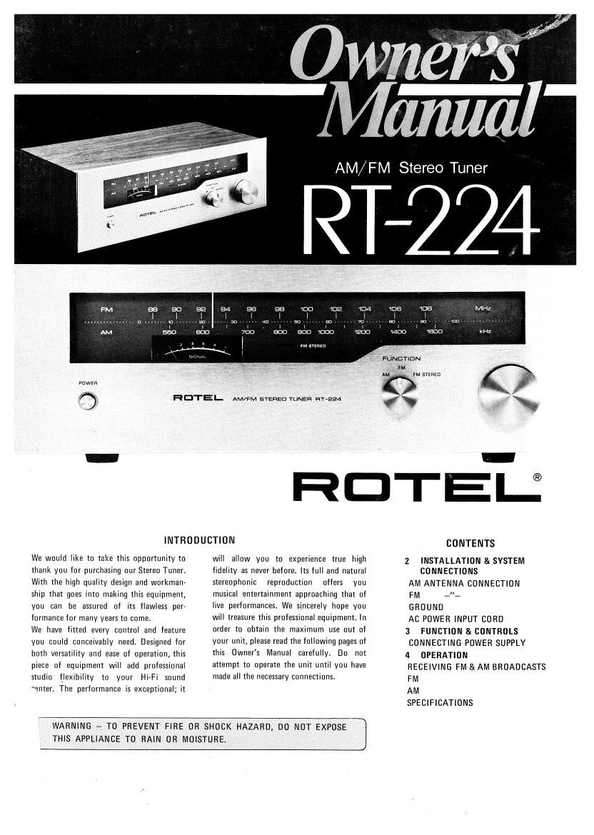
Rotel RT 224 OM

This is the 3 pages manual for Rotel RT 224 OM.
Read or download the pdf for free. If you want to contribute, please mail your pdfs to info@audioservicemanuals.com.

Page: 1 / 3
left right
Rotel RT 224 OM

Extracted text from Rotel RT 224 OM (Ocr-read)


Page 1

RDTEI- AM/FM STEREO TUNER nr-eea

AM/ FM Stereo Tuner

..............................

w stanza


RDTE-u

INTRODUCHON

We would like to take this opportunity to
thank you for purchasing our Stereo Tuner.
With the high quality design and workman»
ship that goes into making this equipment,
you can be assured of its flawless per-
formance for many years to come.

We have fitted every control and feature
you could conceivably need. Designed for
both versatility and ease of operation, this
piece of equipment will add professional
studio flexibility to your Hi-Fi sound
enter. The performance is exceptional; it

will allow you to experience true high
fidelity as never before. Its full and natural
stereophonic reproduction offers you
musical entertainment approaching that of
live performances. We sincerely hope you
will treasure this professional equipment. In
order to obtain the maximum use out of
your unit, please read the following pages of
this Owners Manual carefully. Do not
attempt to operate the unit until you have
made all the necessary connections.

THIS APPLIANCE TO RAIN OH MOISTURE.

WARNING - TO PREVENT FIRE OR SHOCK HAZARD, DO NOT EXPOSE J

CONTENTS

2 INSTALLATION 8i SYSTEM
CONNECTIONS

AM ANTENNA CONNECTION
FM ~"~

GROUND

AC POWER INPUT CORD

3 FUNCTION 8: CONTROLS
CONNECTING POWER SUPPLY
4 OPERATION

RECEIVING FM & AM BROADCASTS
FM

AM

SPECIFICATIONS

Page 2

INSTALLATION
First, make sure that all the necessary
connections are properly made.

AM ANTENNA CONNECTION

No external antenna will generally be re»
quired for AM broadcast listenings, since a
ferrite loopstick antenna is supplied at the
rear of the unit. For best possible reception,
extend the loopstick fully away from the
tuner chassis.

If you live in a difficult reception area, the
use of an external or outdoor antenna may
be desireable.

Connect a single wire antenna lead to the
terminal marked AM on the rear chassis.
The single wire antenna ("hay" or a kind of
"whip") should then be longer as possible,
and oriented for best reception. It must be
kept away from large metal objects, power
lines or electrical machinery to insure better
reception to avoid extraneous noises.


OUTDOOR
AM ANTENNA

GROUND


' LEFT
OUTPUT

TUNER INPUT

O 0000 O
©©OO?9???? 0

FM ANTENNA CONNECTION

Owning to the high sensitivity of the FM
Tuner stage of the unit, the antenna wire
(twin-T" shape, window shead) supplied is
sufficient for most locations.

Connect this feed line ends to both termi-
nals marked 300 ohms; FM ANT, and
mount this twin-T horizontally, for ex-
ample, by tacking both ends to the shelf
front edge on which the receiver is located.
In case weak signal area, the use of an
outdoor type exclusive FM antenna may
prove necessary. Follow its instructions for
proper connections.

When using a 75-ohm unbalanced coaxial
cable to feed signals from antenna, connect
them to terminal posts marked a 75-ohm
and G-terminal with the outer conductor or
shielding blade of the cable, or use the
coaxial adaptor socket marked 75-ohm.

GROUND

Although it is not necessary to do so,
however, if you wish to take the tuner to be

INDOOR
FM ANTENNA 3000

:

STEREO
PRE-MAIN AMPLIFIER

ANTENNA

earthed to eliminate unwanted noises possi-
ble, connect a wire from the terminal
designated GND on the rear chassis to the
ground terminal on your amplifier or to a
nail burried under ground.

AC POWER INPUT CORD (AC MAINS)
Your tuner has been specially designed so
that it may be connected to a variety of
power sources. You may connect the AC
Power Input Cord directly to a wall outlet
in case when the power will be supplied to
the tuner independently from your ampli-
fier. Or, you may connect it to your
amplifiers switched or unswitched AC out-
let. If it is connected to a switched outlet,
by leaving the power button of the tuner
on, you will be able to maintain switching
control for the tuner with your amplifier
together. If it is connected to an unswitched
outlet, like connecting to a wall outlet you
must use the tuners own power button for
switching control.

OUTDOOR
FM ANTENNA 75.0.


AC POWER
CORD

Ill

AC OUTLETS

POWER SWITCH:

turns on and supplies AC mains power to
the unit. When the switch is ON, the dial
scale of the unit illuminates at the same
time.

HOTEL

m "snip

AM/FM STEREO 1 NER HT-EEA

TUNING KNOB:
tion allows easy and precise tuning on both
AM and FM stations.

PM man:

SIGNAL STRENGTH TUNING METER:
shows the level of the incoming signal.
When used with the TUNING KNOB tune in
for maximum meter pointer deflection to
the right to the desired best possible recep-
tion of AM or FM broadcast.

STEREO INDICATOR LIGHT: auto-
matically lights up on the dial scale glass to
visually indicate whenever an FM stereo
braodcast is tuned in.

CONNECTING TO POWER SUPPLY

Prior to connection ensure that the voltage
selector is set correctly for your local AC
mains supply, and a suitable plug fitted. If
you need to fit a plug, make sure also that a
live, neutral and (where appropriate) earth
leads are connected to the proper terminals.
If in any doubt about connection to the
mains supply, consult a qualified technician.

COAXIAL CABLE:

cable connector to a chassis socket of the
tuner firmly and gently tighten the outer
connector cover turning it clockwise.
Advantage of using coaxial cable is to shut
off external noise fed through feed line
which usually affects tuners front-end.

FUNCTION SELECTOR CONTROL: En-
ables you to select the program you desire
from AM, FM or FM STEREO. During
monophonic FM reception a stereo in»
dicator light provided on the unit will light
on automatically when the broadcast station
has switched to FM stereo program.

If you live in U.K., please read
EXCLUSIVE NOTE FOR U.K.
on the last page.