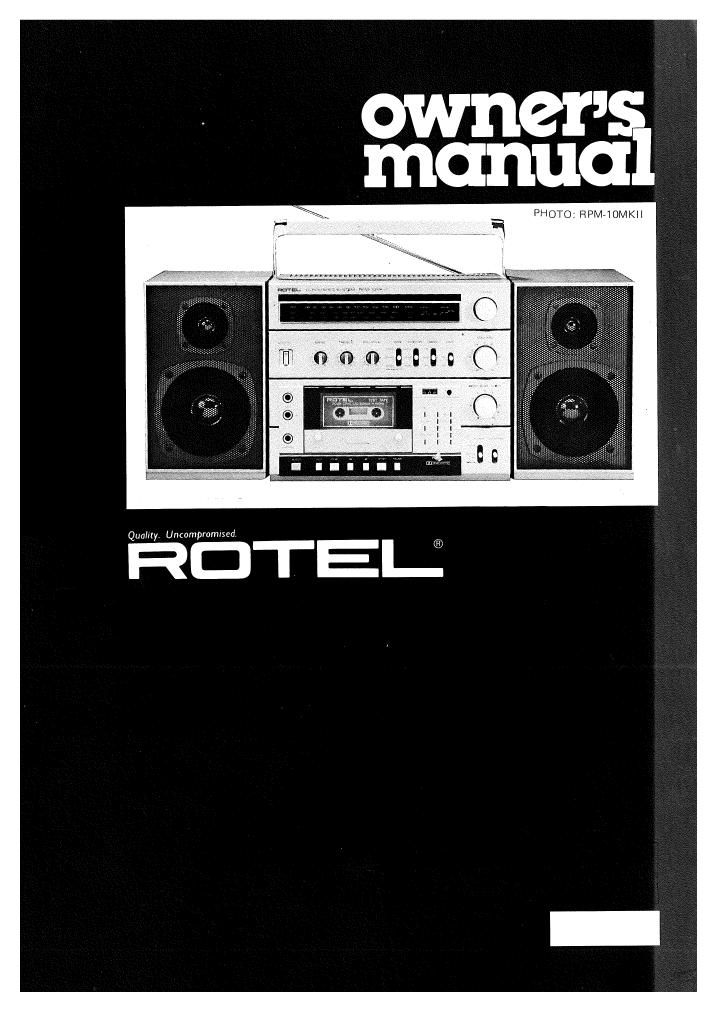
Rotel RPM 10 10S OM

This is the 5 pages manual for Rotel RPM 10 10S OM.
Read or download the pdf for free. If you want to contribute, please mail your pdfs to info@audioservicemanuals.com.

Page: 1 / 5
left right
Rotel RPM 10 10S OM

Extracted text from Rotel RPM 10 10S OM (Ocr-read)


Page 2

llllillSH

MW/LW/FM STEREO PORTABLE MICRO SYSTEM RPM~1O
MW/SW/FM STEREO PORTABLE MICRO SYSTEM RPM-10$

INTRODUCTION

We at Hotel want to thank you for purchasing
our audio product.

Hotel audio products are designed to use the
latest electronic technology, and they incorpo-
rate our long experience as a specialist manufac-
turer of audio equipment We are confident
that you will find satisfaction in the high
quality sound and top performance, and that
you will find pleasure in the functional beauty
achieved through human»engineering concept.
Before starting operation, please read this
instruction manual thoroughly and acquaint
yourself with the proper mode of using the unit
and all its connections:

We hope you will enjoy top-notch performance
for many years to come.

BEFORE ENJOYMENT

Follow the instructions below for maximum
safety:

1. Installation

Be sure to place the unit in a level and flat place
where it is free from humidity, vibration, high
temperature and not exposed to direct sunlight.
2. Vantilato the unit wall

Never block any ventilation holes at the top
and bottom of the unit. Be sure also to provide
ample ventilation space around the unit. Poor
ventilation may result in damage due to exces-
sive heat.

3. Do not open the cabinet

In order to avoid electric shock or damage to
the component, never open the cabinet. It a
foreign object falls inside the unit by mistake,
turn the power off, disconnect the wall plug,
and consult a qualified electrician or your
italer.

4. If the unit gets wet

If the unit should get wet, immediately discon-
nect the AC cord. and consult your dealer or a
qualified electrician.

5. Cleaning and maintenance

Do not use chemicals such as benzine or thinr
ners on the front panel. Always use a soft, dry
cloth to clean the unit,

8. Owner's manual

Keep the owner's manual near the unit, and
record the serial number (found on the rear
panel) on the cover.


EXCLUSIVE NOTE FOR U.K.
Connecting Bulgin Plug


If your unit comes with a 2-core cable
without a plug, make certain live and
neutral leads are connected to the proper
termlnals. Check that the terminals are
screwed down firmly and no loose strands
of wire are present.

IMPORTANT: The Wires in this mains lead
are coloured in accordance with the follow-


ing code:
BLUE: NEUTRAL
BROWN: LIVE

As the colours of the wires in the mains lead
of this apparatus may not correspond with
the coloured markings identifying the
terminals in your plug proceed as follows.
The wire which is coloured BLUE must be
connected to the terminal which is marked
with the letter N or coloured BLUE or
BLACK. The wire which is coloured

BROWN must be connected to the terminal
which is marked with the letter L or colour»
ed BROWN or RED.

POWER SOURCES

When plugging in or unplugging the RPM-10(5).
or when inserting or removing the batteries,
first make sure the power switch on the main
unit is turned off,

0 Household AC

Connect the supplied AC power cord to AC IN
socket on the rear of the main unit, and then
to a wall outlet. when the cord is plugged
into the AC IN socket, the internal batteries (if
inserted) are automatically disconnected.

WA LL OUTLET

A: to:
EXT 1 2v

a Batteries
Open the battery compartment lid on the rear

by pushing on the two notched portions in
the direction of the arrows.

oeo
6369

Insert eight SUM-1 ("D") batteries into the
compartment, correctly matching the polarity
markings inside the compartment. When the
RPM-10(8) is not used for a long period, or is
operated extensively on AC power, be sure to
remove batteries. This will prevent possible

trouble caused by battery leakage.
NOTE FOR THE 12V BATTERV INPUT

The 12V Input not being provided with e Fuse
in the equlpment. The fuse mustbe inserted in
the Circuit between external battery and 12v
input.

Note: When the batteries grow weak, sound
quality will deteriorate and/or the tape trans-
port motion will become unstable. Weak bat-
teries should be promptly replaced with new
ones. Be absolutely certain to replace ALL
eight batteries at once

When making an important recording, it is
advisable to use new batteries.to insure opti-
mum performance '

0 12V Car Battery

By using a car battery cord, the RFMr10lS)
can be powered through the cigarette lighter
socket of a car. (The unit cannot be operated

on 24-volt type car battery.)
aowaa

or? .-

CIGARETI'E LIGHTER
SOCKET

Dc
EXT 12v

To connect the car battery cord, insert the
larger plug into the cigarette lighter socket, and
the other plug into the DC IN socket on the
RPM-10(8). Be sure the AC power cord is dis-
connected trom the main unit when using the
car battery cord. When the car battery cord is
connected, internal batteries (if present) are
automatically disconnected.

SPEAKERS

The accompanying speakers can be either at-
tached to the main unit or separated from it.
That speaker with the mounting plate on the
right side (as seen from the front) is the left-
chennel speaker, and the other, with mounting
plate on left, is the right-channel speaker.

Attaching Speakers to the Main Unit

Mount both speakers on the main unit by fit-
ting the hole of the speaker mounting plate
onto the shaft joint of the main unit carrying
handle. Next, lay out the combined compo-
nents with rear panel down. Locate the two
speaker fixing plams on the bottom of the unit.
Loosen the screw on each fixing plate. Slide out
each plate, and hook the hole in the plate onto
the dowel provided on the bottom of speaker.
Then, slide each plate back until the speaker
comes in firm contact with the main unit.

ll

61.

Tighten both screws to fix the speakers securely
in place.


MAIN UNIT
SPEAKER

MAIN UNIT

7

czzjzzo

Connecting Speaker Cables

Using the supplied speaker cables, connect
the left-channel speaker to the leftvhand speak»
er terminals on the rear of main unit, and the
right-channel speaker to the right-hand speaker
terminals, correctly matching the polarities.

To hook up the cable with the terminal, insert
the end of the cable into the hole while pushing
on the button. Then release the button. The
cable should be firmly fixed in place.


SPEAKER
(RIGHT)

CONNECTING TURNTABLE

Connect the two pin plug cords extendingfrom
the turntable to the PHONO terminals on the
rear of the main unit, making correct left (L)
and right (R) channel connections. Then conv
noct the grounding Wire of the turntable to

the GNU terminal.

ANTENNA
FM

On the rear of the main unit is an FM rod
antenna. For FM reception, pull up and extend
the antenna, and adjust its length, angle end
orientation until optimal reception is obtained.
Caution: Do not carry the unit while the FM
rod antenna is in raised position, to prevent
damage to the antenna,

AM

An AM ferrite bar antenna is built into the
main unit. The FM rod antenna is not effective
for AM reception.

The internal AM antenna is directional, so
when AM reception is difficult, try rotating the
unit horizontally to change antenna orienta-
tinn.

External FM Antenna

If you are in a steel-frame building or considera-
bly far from broadcasting stations, the unit rod
antenna may not provide satisfactory FM
reception. In that case, connect an external
FM antenna to the antenna terminals on the
rear panel.

Use terminals labeled 759." for 75-ohm
coaxial cable: Connect the center conductor
of the cable to the left-hand terminal, and
connect the outer braided conductor of the
cable to the right-hand terminal.

Use terminals labeled "3009"
antenna with feeder wires.

Note: If your unit has a coaxial connector,
attach an adaptor to the coaxial cable and
insert the adaptor into the connector.

to connect

AUTOMATIC SH UTOFF SYSTEM
OF CASSETTE DECK SECTION

To protect the RPM-10(8) motor and transport
mechanism against unnecessary wear. an auto-
matic shutoff device has been built into the
unit. When either end of tape is reached in
play, record, fast-forward, or rewind mode, the

motor and mechanism will automatically shut
off, disengaging the present mode.

CASSETTE TAPES

0 To prevent possible trouble with the trans~
port mechanism, use of large size cassette tapes,
such as C-1 20, is not recommended.

0 Handle cassette tapes with care. Keep
them away from heat, circulating dust, or a
magnetic field (eg. on the TV set).

0 Each cassette tape has safety tabs on its
back edge to prevent accidental re-recording.
The tabs are provided for both sides of cassette
tape. You cannot record on the side whose tab
has been removed. The tab can be removed
with a screwdriver, etc. If you wish to record
on the side with no tab. place a piece of adhe-
sive tape, etc. over the opening where the tab
has been, then you can record.

0A loosened tape may cause trouble in
playback or recording. Check the tape before
loading it into the deck. If it is slack, insert a
pencil or the like into either of cassette's hubs.
and rotate it carefully until the slack is taken

Outdoor Antenna Grounding

See figure.

and lead-in.

in enters house.

caouuo /
cum»
str
onounn
wlnz ls. er

Satan ii

EXCLUSIVE NOTES FOR THE U.S.A.

If an outside antenna is connected to the receiver/tuner, be sure the an-
tenna system is grounded so as to provide some protection against vol-
tage surges and built up static charges. Section 810 of the National
Electrical Code, ANSI/NFPA No. 70-1978, provides information with
respect to proper grounding of the mast and supporting structure,
grounding of the lead-in wire to an antenna discharge unit, size of
grounding conductors, location of antennadischarge unit, connection
to grounding electrodes. and requirements for the grounding electrode.

3. Use No. 10 AWG copper or No. B AWG aluminum or No. 17 AWG
copper-clad steel or bronze wire, or larger as ground wires for both mast

b. Secure lead-in wire from antenna to antenna discharge unit and mast
ground wire to house with stand-off insulators, spaced from 4 feet
(122 meters) to 6 feet (1.83 meters) apart.

c. Mount antenna discharge unit as closely as possible to where lead-


deNtEAo on
(,trxa mwiac
la,hl

4- T0 RPM-10 (10$)

canola
WM \nnn.

DrscHAncE

\ UN" It)

a . anuub
/ cuws

L e SUIYABLE Gnouwowt.
atacmooa paws"
a- mo TNE exam
0 u Mrrsnsl