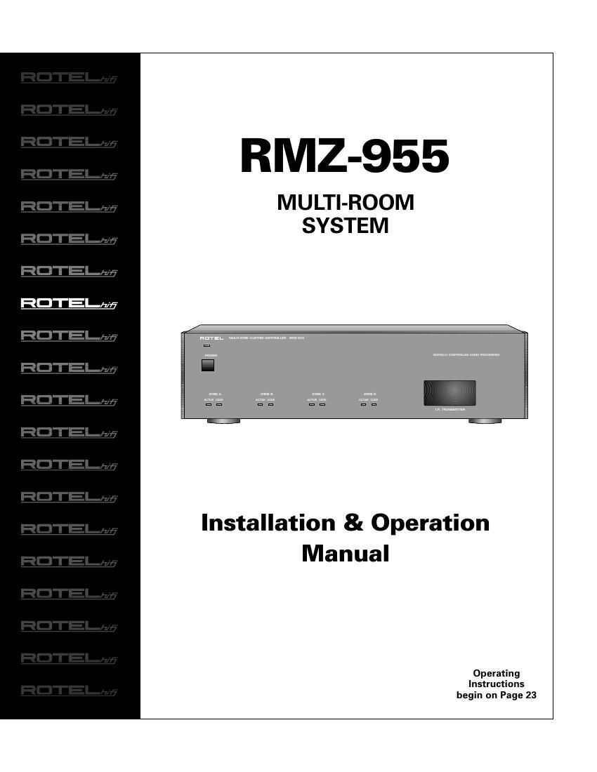
Rotel RMZ 955 OM

This is the 32 pages manual for Rotel RMZ 955 OM.
Read or download the pdf for free. If you want to contribute, please mail your pdfs to info@audioservicemanuals.com.

Page: 1 / 32
left right
Rotel RMZ 955 OM

Extracted text from Rotel RMZ 955 OM (Ocr-read)


Page 1

MULTI-ROOM SYSTEM CONTROLLER RMZ-955 2 CAUTION: TO PREVENT ELECTRIC SHOCK, MATCH WIDE BLADE OF PLUG TO WIDE SLOT. INSERT FULLY. APPLICABLE FOR USA, CANADA OR WHERE APPROVED FOR THE USAGE ATTENTION: POUR EVITER LES CHOCS ELECTRIQUES, INTRODUIRE LA LAME LA PLUS LARGE DE LA FICHE DANS LA BORNE CORRESPONDANTE DE LA PRISE ET POUSSER JUSQU AU FOND. CAUTION RISK OF ELECTRIC SHOCK DO NOT OPEN CAUTION: TO REDUCE THE RISK OF ELECTRIC SHOCK, DO NOT REMOVE COVER. NO USER-SERVICEABLE PARTS INSIDE. REFER SERVICING TO QUALIFIED SERVICE PERSONNEL. This symbol is to alert the user to the presence of uninsulated dangerous voltages inside the product's enclosure that may constitute a risk of electric shock. This symbol is to alert the user to important operating and maintenance (service) instructions in this manual and literature accompanying the product. WARNING: There are no user serviceable parts inside. Refer all servicing to qualified service personnel. WARNING: To reduce the risk of fire or electric shock, do not expose the RMZ-955 to moisture or water. Do not allow foreign objects to get into the enclosure. If the unit is exposed to moisture, or a foreign object gets into the enclosure, immediately disconnect the power cord from the wall. Take the unit to a qualified service person for inspection and necessary repairs. Read all the instructions before connecting or operating the RMZ-955 . Keep this manual so you can refer to these safety instructions. Heed all warnings and safety information in these instructions and on the product itself. Follow all operating instructions. Clean the RMZ-955 only with a dry cloth or a vacuum cleaner. Keep the ventilation inlets on the unit unobstructed. For example, do not place the unit on a bed, sofa, rug, or similar surface that could block the ventilation slots. If the RMZ-955 is placed in a bookcase or cabinet, there must be suffi- cient clearance around the unit and ventilation of the cabinet to allow proper cooling. Keep the RMZ-955 away from radiators, heat registers, stoves, or any other appliance that produces heat. The RMZ-955 must be connected to a power supply only of the type and volt- age specified on the rear panel of the unit. Connect the RMZ-955 to the power outlet only with the supplied 3-pin polarized grounded power supply cable or an exact equivalent. Do not modify the sup- plied cable in any way. Do not attempt to defeat grounding and/or polarization provisions. The cable should be connected to a 3-pin polarized grounded wall outlet, matching the wide blade of the plug to the wide slot of the receptacle. Do not use extension cords. Do not route the power cord where it will be crushed, pinched, bent at severe angles, exposed to heat, or damaged in any way. Pay particular attention to the power cord at the plug and where it exits the back of the unit. The power cord should be unplugged from the wall outlet if the unit is to be left unused for a long period of time. Immediately stop using the RMZ-955 and have it inspected and/or serviced by a qualified service agency if: ¥ The power supply cord or plug has been damaged. ¥ Objects have fallen into or liquid has been spilled into the unit. ¥ The unit has been exposed to rain. ¥ The unit shows signs of improper operation ¥ The unit has been dropped or damaged in any way Place the RMZ-955 on a fixed, level surface strong enough to support its weight. Do not place the RMZ-955 on a moveable cart that could tip over. 123456 MULTI-ZONE CUSTOM CONTROLLER RMZ-955 ZONE A ACTIVECODE ZONE BACTIVECODE ZONE CACTIVECODE ZONE DACTIVECODE DIGITALLY CONTROLLED AUDIO PROCESSING I.R. TRANSMITTER INPUTS2 3 4 1 IN OUT IN OUT IN OUT IN OUT RLRC-5 N/C MULTI-ZONE CUSTOM CONTROLLER MODEL NO. RMZ-955 POWER CONSUMPTION: 430W AC120V ~ 60HZ DESIGNED AND MANUFACTURED IN ENGLAND SPEAKER IMPEDANCE 4 OHM MINUMUM TX-FORMATT X O U T P U T S POWER ZONE B DATA 123456PRE-OUT DATA 123456PRE-OUTSPEAKERS SPEAKERS SPEAKERS SPEAKERSZONE D DATA 123456PRE-OUT DATA 123456 PRE-OUTZONE C ZONE A WE1 WE2 WE3 WE4 CAUTIONRISK OF ELECTRIC SHOCK DO NOT OPEN ~ CAUTIONRISK OF ELECTRIC SHOCK DO NOT OPEN WARNING: TO REDUCE THE RISK OF FIRE OR ELECTRICAL SHOCK DO NOT EXPOSE THIS EQUIPMENT TO RAIN OR MOISTURE. Ð+Ð+LEFT RIGHT Ð+Ð+LEFT RIGHT Ð+Ð+LEFT RIGHT Ð+Ð+LEFT RIGHT PAGING TRIGGER AUDIO IN AUDIO OUT UNSWITCHED SWITCHED LINK IN LINK OUT ZONE D MULTI-ZONE CUSTOM CONTROLLER RMZ-955 ZONE A ACTIVECODE ZONE BACTIVECODE ZONE CACTIVECODE ZONE DACTIVECODE DIGITALLY CONTROLLED AUDIO PROCESSING I.R. TRANSMITTER POWER INPUTS2 3 4 1 IN OUT IN OUT IN OUT IN OUT RLRC-5 N/C TX-FORMAT 123456 ZONE B DATA 123456PRE-OUT DATA 123456PRE-OUTSPEAKERS SPEAKERS SPEAKERS SPEAKERS DATA 123456PRE-OUT DATA 123456 PRE-OUTZONE C ZONE A T X O U T P U T S WE1 WE2 WE3 WE4 ~ RC-5 N/C MULTI-ZONE CUSTOM CONTROLLER MODEL NO. RMZ-955 POWER CONSUMPTION: 430W AC120V ~ 60HZ DESIGNED AND MANUFACTURED IN ENGLAND WARNING: TO REDUCE THE RISK OF FIRE OR ELECTRICAL SHOCK DO NOT EXPOSE THIS EQUIPMENT TO RAIN OR MOISTURE. SPEAKER IMPEDANCE 4 OHM MINUMUM CAUTIONRISK OF ELECTRIC SHOCK DO NOT OPEN Ð+Ð+LEFT RIGHT Ð+Ð+LEFT RIGHT Ð+Ð+LEFT RIGHT Ð+Ð+LEFT RIGHT PAGING TRIGGER AUDIO IN AUDIO OUT UNSWITCHED SWITCHED LINK IN LINK OUT

Page 2

3 Getting Started 4 Controlling the Remote Zones 4 System Flexibility 4 System Highlights 4 Component Description _______________________________ 4 RMZ-955 Controller/Amplifier 4 System Planning _____________________________________ 4 RR-952 IR Remote Control 5 RSM-901 Sensor/Display 5 RKP-901 Keypad 5 RSM-901/RKP-901 Combination 5 Placement 6 Connections: 6 IR Flood Emitter 6 IR Repeater Jacks 6 System Wiring Considerations ________________________ 6 Data Cable and Connectors 6 Speaker Cables 7 Zone Configuration ___________________________________ 7 Basic Zone Complement 7 Loudspeakers 7 Installation: RMZ-955 Controller 8 AC Line Connections _________________________________ 8 AC for the RMZ-955 8 AC for Source Components 8 Rotel RLC-900 AC line conditioner/switcher 8 Special AC features 8 Source connections __________________________________ 9 Source inputs 9 Source outputs 9 Speaker Connections ________________________________ 10 Preamp outputs _____________________________________ 11 Variable vs. Fixed Level 11 Data cable connections ______________________________ 12 Infrared Control System _____________________________ 13 Front Panel IR Flood Emitter 13 Rear Panel IR Repeaters 13 Paging Input ________________________________________ 14 Paging Inhibit 14 Installation: Zone Control Devices 15 RSM-901 Sensor/Display _____________________________ 15 RSM-901 Mounting 15 RSM-901 Data Connections 16 Battery Enable 16 Zone Configuration 16 Source Component Labels 16 Master/Slave Configuration 16 System Reset 17 Source Component Set-up 17RKP-901 Keypad _____________________________________ 17 RKP-901 Mounting 17 RKP-901 Data Connections 17 Zone Connection Strategies __________________________ 18 Installation: Multi-controller Systems 18 AC Power ___________________________________________ 20 AC Connections 20 AC Link 20 Manual AC Override 20 Source Connections _________________________________ 20 IR Connections ______________________________________ 21 For 2 RMZ-955s (5 to 8 zones): 21 For 3 RMZ-955s (9-12 zones): 21 For 4 RMZ-955s (13-16 zones): 22 Exception: Multiple IR Flood Emitters 22 Paging Connections 22 Notes on multi-controller set-up ______________________ 23 Power Toggle Set-up 23 Source Component Set-up 23 ÒEngagedÓ Indicator 23 System Set-up & Programming 24 Source Commands __________________________________ 24 Source Command Set-up ____________________________ 24 Power Toggle _______________________________________ 25 Operating Instructions 26 RR-952 Hand-held Remote ___________________________ 26 Input Selector Buttons 26 Tuner control buttons 26 CD control buttons 27 Tape/Satellite TV control buttons 27 Video/LD control buttons 27 Mute 27 VOLUME UP/VOLUME DOWN 27 STBY 27 ÒXÓ 27 RKP-901 Keypad _____________________________________ 28 Input Select commands 28 System commands 28 Source Control Commands 28 RSM-901 Sensor/Display _____________________________ 29 Controls and Displays 29 Dot Matrix Display 29 Setting Alarm, Time, and Custom Functions 30 For Assistance ______________________________________ 31 CONTENTS

Page 17

MULTI-ROOM SYSTEM CONTROLLER RMZ-955 18 aaaaaaaaaaaaaaaaaaaaaaaaaaaaaaaa Zone Connection Strategies Each zone will support up to three RSM-901s and three RKP-901s. All of the command devices for one zone should con- nect to each other in serial fashion using their appropriate cir- cuit board-mounted ÒInÓ and ÒOutÓ terminals. Each RSM-901 signals when it receives and processes a com- mand. This happens regardless of whether the command was generated by a keypad or a hand held remote. However, a key- pad located ÒdownstreamÓ of a sensor/display will not trigger that sensorÕs command processing indicator. Whenever possible, we suggest that you configure each zone so that all keypads are ÒupstreamÓ from all sensor/displays. Al- though not always practical depending on the zone configura- tion, this arrangement will reduce user confusion. Regardless of other considerations, we suggest that you always wire an RSM/RKP double wall box so that the RSM is located ÒdownstreamÓ from adjacent RKP (i.e., between the RKP and the RMZ-955 controller/amplifier). This assures that the sensor/dis- play always signals the user when the adjacent keypad is used. Installation is the first step towards enjoying an RMZ-955 system. Proper set-up ensures that the RMZ-955 will function optimally with all associated source components and provide total system control. Installation: Multi-controller Systems Each RMZ-955 provides independently controlled audio distribu- tion from four sources to four separate zones. To satisfy the re- quirements of more elaborate systems, up to four RMZ-955s can be cascaded to build a system with as many as 16 independent zones. Under these circumstances, all RMZ-955 controller/ampli- fiers share one set of four source components. When system complexity calls for more than one RMZ-955, we have no cautions about stacking controller/amplifiers on top of each other. As long as there is sufficient room to allow relatively unrestricted air flow, heat should not be a problem. In most respects, installing a multi-controller system is no differ- ent than a single controller system. Source input connections, speaker output connections, data cable connections to the re- mote zones, and other configuration steps are essentially the same. Review Installation: RMZ-955 Controller (page 5) for com- plete information. There are, however, some additional considerations and installa- tion steps required for a system with multiple RMZ-955 control- lers. These steps all deal with the need to link the controllers: a) AC connections for fully-integrated system control b) Sharing four sources among all controllers c) Passing IR commands from one controller to the rest d) Linking special features like system-wide paging All hookup instructions in this section assume that Zones 1-4 will be handled by the first RMZ-955 (called ÒAÓ), Zones 5-8 by the RMZ-955 immediately above it (ÒBÓ), Zones 9-12 by third unit (ÒCÓ), and Zones 13-16 by the top unit (ÒDÓ). In most cases, we do not illustrate all four controllers, as additional controllers are merely added in the same fashion as the second or third con- troller. There is no functional distinction between the first RMZ-955 and additional controllers in a system. However, for convenience and simplicity, we assume that the first controller will handle some additional responsibilities, such as source inputs and sending IR signals to the sources. This approach makes it easy on the in- staller, particularly when starting with a single RMZ-955 and later expanding with additional controllers. Essentially, the work done installing a single RMZ-955 remains unchanged and additional zones are handled by Òadd-onÓ RMZ-955 controllers.