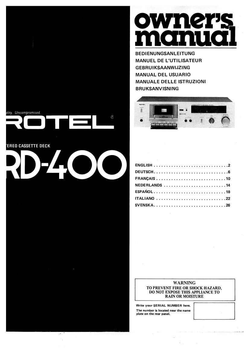
Rotel RD 400 OM

This is the 16 pages manual for Rotel RD 400 OM.
Read or download the pdf for free. If you want to contribute, please mail your pdfs to info@audioservicemanuals.com.

Page: 1 / 16
left right
Rotel RD 400 OM

Extracted text from Rotel RD 400 OM (Ocr-read)


Page 1

owner 5
manual

BEDIENUNGSANLEITUNG
MANUEL DE L'UTILISATEUR
GEBRUIKSAANWIJZING
MANUAL DEL USUARIO
MANUALE DELLE lSTRUZlONI
BRUKSANVISNING

try Uncompronmed.

EREO CASSETTE DECK

. - ENGLISH .............................. 2
DEUTSCH .............................. 6
FRANQAIS ............................ 1o

N E DE R LANDS ......................... 14

ESPANOL ............................. 18

ITALIANO ............................ 22

SV ENSKA ............................. 26
WARNING

TO PREVENT FIRE OR SHOCK HAZARD,
DO NOT EXPOSE THIS APPLIANCE TO
RAIN 0R MOISTURE

Write your SERIAL NUMBER here.

The number is located near the name
plats on the rear panel.

Page 2

ENGLISH

STEREO CASSETTE DECK RD-400

INTRODUCTION

We at Rotel want to thank you for
purchasing our abdio product.

Rotel audio products are designed
to use the latest electronic techno-
logy, and they incorporate our long
experience as a specialist manufac-
turer of audio equipment. We are
confident that you will find satis-
faction in the high quality sound
and top performance, and that you
will find pleasure in the functional
beauty achieved through human-
engineering concept. Before start-
ing operation, please read this
instruction manual thoroughly and
acquaint yourself with the proper
mode of using the unit and all
its connections.

We hope you will enjoy topvnotch
performance for many years to
come.

INSTALLATION

Be sure to place the unit in a level
and flat place where it is free from
humidity, vibration, high tempera-
ture and not exposed to direct
sunlight. Be careful not to place the
unit in a highly enclosed place such
as near a wall or on a bookshelf. A
poor ventilation will cause undesira-
ble effects to the unit.

POWE R SUPPLY
CONNECTION

For power the unit requires the
normal house electrical current

(AC). You may simply plug the
unit into a wall outlet, or into your
amplifiers switched or unswitched
AC outlet. If it is plugged into a
switched outlet, by leaving the
power switch of the unit on, you
will be able to maintain switch-
ing control for the RD-400 with
your amplifier. If it is connected to
an unswitched outlet, like connect-
ing to a wall outlet you must use
the R0400; own power switch
for switching control.

CAUTION: Do not apply power
without first making sure the
proper connections are completed.
If you live in U.K. and your unit
comes with 2-core cord without a
plug, be sure to read the exclusive
caution for U.K.

IMPORTANT: The wires in this
mains lead are coloured in ac-
cordance with the following

oeed as follows.
The wire which is coloured
BLUE must be connected to the

EXCLUSIVE NOTE FOR
U.K.

If your unit comes with a 2- code: terminal which is marked with
core cable without a plug, make BLUE: NEUTRAL the letter N or coloured BLUE
certain live and neutral leads BROWN: LlVE or BLACK. The wire which is

coloured BROWN must be con-
nected to the terminal which is
marked with the letter L or
coloured BROWN or RED.

As the colours of the wires in
the mains lead of this apparatus
may not correspond with the
coloured markings identifying
the terminals in your plug pro-

are connected to the proper
terminals. Check that the ter-
minals are screwed down firmly
and no loose strands of wire are
present.

CONNECTION TO INTE-
GRATED AMPLIFIER

Two pairs of RCA cords for LINE
lN/OUT extend out from the rear
panel of the cassette deck. The cord
from the LINE IN terminals of the
deck should be plugged into the
TAPE MONITOR OUT terminal of
the amplifier, and the cord from
LINE OUT terminal to the TAPE
MONITOR lN terminal. RCA cords
with white plugs are for left chan-
nel (L) connection, and cords with
red plugs are for right channel IR).

LINE
IN OUT

INTEGRATED AMPLIFIER
(RECEIVER)

SWITCHES AND CONTROLS

(1) Power Button

Depressed once, this button turns
on powerin the tape deck. Pressed
a second time, the button is re-
leased and the unit is turned off.

(2) Headphone Jack

For headphone listening from the
deck the headset is plugged into
this jack. Before beginning, make
sure the volume control of your
amplifier is set to minimum.

(3) Cassette Mechanism
Controls

STOP/EJ ECT Button

This button is used to disengage the
recording, playback, fast-forward,
or rewind mode. After stopping the
tape, release the button, then press
all the way down to open the cas-
sette door for removal of cassette
tape. Also use this button when
inserting the cassette.

REC Button

Used to put the deck in the record-
ing mode. To record, simultaneous-
ly depress this button and PLAY
button.

REW Button

Depress this button to rapidly re»
wind the tape.

PLAY Button

Used to play back prerecorded
tape. When depressed, the deck is
put in the play mode and the tape
starts. Depress the same button
simultaneously with the REC but-
ton when going into the recording
mode. The button will disengage
automatically when the end of the
tape is reached in either playback
or recording mode, to protect the
tape and the cassette mechanism.

iD


HOTEL

miwm

Ernie/Edict urx. new
>

F. FWD Button

Depress this button to advance the
tape rapidly forward.

PAUSE Button

Depress this button to temporarily
halt tape travel when in recording
or playback mode.

Pressing the button a second time
will restart the tape, returning to
the interrupted mode.

(4) Microphone Jacks

When making live recording with
stereo microphones, insert the mi-
crophone plugs into these jacks.
Make sure the right-hand micro~
phone is connected to the right
channel jack, and the left-hand min
crophone to die left channel jack.
Be sure to unplug the microphones
when recording from other sources.
(5) Dolby NR Sviiitch

Depress this button to switch in the
built-in Dolby NR circuit provided
for high-frequency range noise re-
duction when you wish to record or

play back through Dolby NR cir-
cult.

(6) Tape Selector

Used to select the appropriate re-
cording bias and playback equa»
Iization, according to type of cas»
sette tape used. Use the METAL
position for metal tape, the SPE-
CIAL position for chromium dioxi~
de tape, and the NORMAL position
for normal tape. See TAPE SE-
LECTOR SETTING GUIDE for
details of various brands of cas-
sette tapes and their proper se-
lector positions.

(7) Recording Level Control

Used to control the recording level
of incoming signals, such as from
a turntable, tuner, or microphones.

a .w Fiwn mus:
»

This is a dual concentric knob
which permits either separate or
combined adjustment of both chan-
nels. Use the outer ring for the left
channel, and the knob for the right
channel.

(8) VU Meters

These meters give instantaneous dis-
play of recording or playback level
for both left and right channels re
spectively. Each meter directly
shows levels from -20dB to+8dB.

(9) Dolby NR Indicator
Glows when Dolby N R switch is on,
indicating the unit is in Dolby NR
recording or playback mode.
(10) Recording Indicator

Glows to indicate recording is in
process when REC button on the

cassette control section is de-

pressed.

(11lTape Counter and Reset
Button

The three-digit tape counter indi-
cates the amount of tape travel.
Push the reset button to set the
counter to "000. This counter is
convenient in finding the beginning
of a specific section of the tape or
checking the amount of the re
maining tape on a cassette.

(12) Tape Holder

Cassette tape is loaded onto this
holder.

AUTOMATIC SHUTOFF
SYSTEM

To protect the RD-400s motor
and drive mechanism against un-
necessary wear, an automatic shut-
off device has been built into the
machine. When the supply hub
stops for any reason the motor and
drive mechanism will automatically
shut off after a short period of time.
The machine is also automatically
shutoff at the end of tape (PLAY,
REC/PLAY, FAST FORWARD and
REWIND modes), disengaging all
locked buttons.

Note: Since this device will not
affect the electronic circuits of the
machine it will still be necessary to
turn off the entire unit by pushing
the power switch.