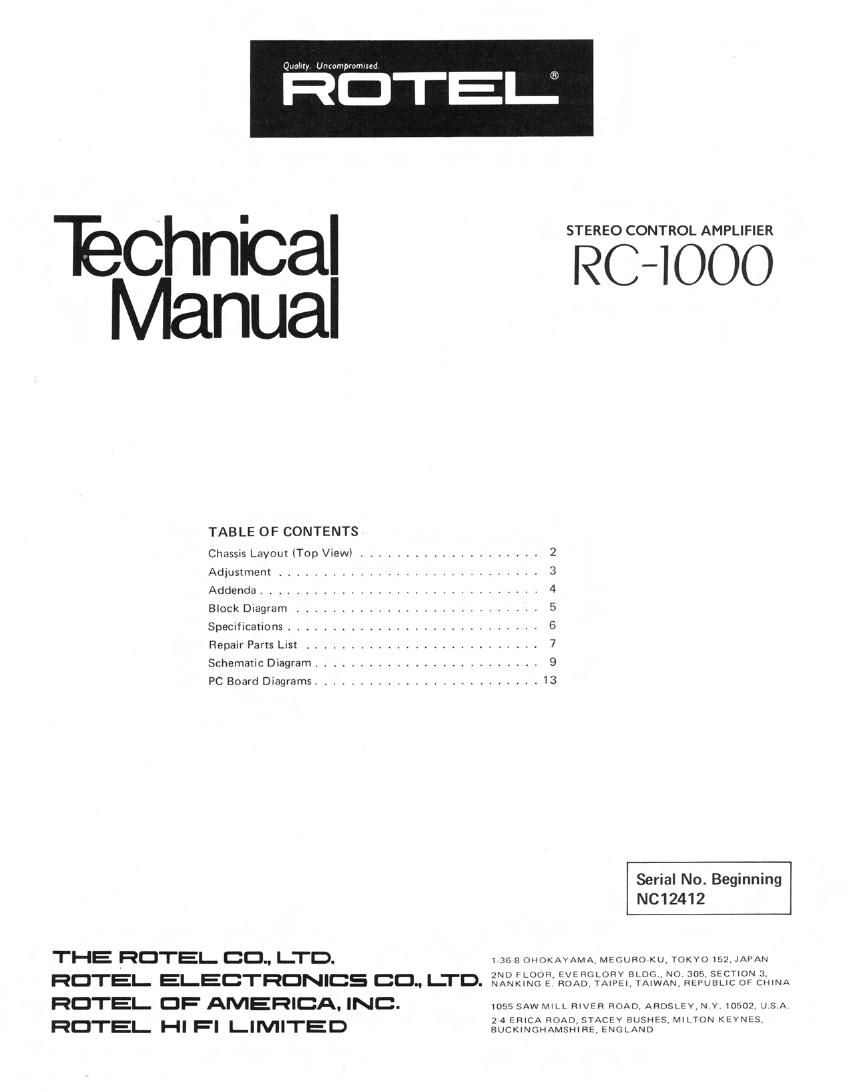
Rotel RC 1000 Service Manual

This is the 12 pages manual for Rotel RC 1000 Service Manual.
Read or download the pdf for free. If you want to contribute, please mail your pdfs to info@audioservicemanuals.com.

Page: 1 / 12
left right
Rotel RC 1000 Service Manual

Extracted text from Rotel RC 1000 Service Manual (Ocr-read)


Page 2

0mm, Unromplnmted

Issue No, ABC-100001 Date 1980-04-10

THE RDTEL 30., LTD.

1-36-8 Ohoklyama, Megurmku, Tokyo 152, Japan

TECHNICAL INFORMATION FOR
MODEL RA- RB- RC-lOOO

0 Errata

nical Manual.

This publication is a supplement to Technical Manual
for the model above, and includes the following,

0 Revisions and changes made on the units produced
after the publication of Technical Manual
This publication should be filed together with the Tech-

A. Errata
1. Page 8, Reapir Parts List, left column, line 6, Part No.

141810956 of Function SW PCB Ass'y should read
141810958.

. Page 11, Schematic Diagram for RC-1000, Phono
Section, simbol Nos. of the capacitors shown in Fig. 1
are corrected as follows: C425 to C427; C426 to
0428.

CORRECT NOS
C477

(C428)


WRONG NOS
C425
(C426

Fig, 1 Phono Amp Circuit (Portion) for PIC-1000

The same correction is applied to the Phono Amp
PCB in page 14. Also, C426 located at the right side
of S2 in the bottom center in the figure should read
0428; and C425 at bottom center inside the alternate
long and short dash line in the MC amp section
should read C427.

Changes in and Addition to Circuit Components
. Changes made to RA-1000 (applicable to the units
with Serial No. beginning NC61910 or over),

a) MC Head Amp Circuit is added to the Phono Amp
Circuit. The Phono Circuit with built-in MC Head
Amp is the same as that of the RC-1000. Because
of this modification, the capacitors C423, and 424
on the Phono Amp Circuit is changed to 100mfd.
+B Circuit is partly modified. Fig. 2 shows the
modified and related portion.

b) Because of this modification, component parts are
added as listed in Table 1 to the models equipped
with built-in MC Head Amp. (Not applicable to
the conventional unit without MC Head Amp.)

Schematic

Location Description Part No.
0401, 402 FET. 28K155lS) 302001123
0403, 404 Transistor, ZSA921 (S, T) 301001145
0405 Transistor, 2SC1318 (R. 51 301201155
D401, 402 Zener Diode, RDSSEC, 3.6V,

0.4W 300313039
D001 Zener Diode, BZ-120, 12V,
1W 300313004

Phono Amp Circuit Board Ass'y 141510174'
Front Panel Ass'y (Metallic

Brown) 111911489
Front Panel Ass'y (Black) 111911490
Rear Panel 123011520
Owners Manual 833201364

Common to the Phono Amp Circuit Board Ass'y for RC~1000.
Note: Repair parts for the models Without MC Head Amp are
as listed "I the Parts List of Technical Manual.

Table 1

. Changes for RB»1000

Some component parts of the power supply for the
units destined for Canada are changed as follows (con-
forming to CSA standards):

a) Power Transformer D»type 204001475
b) Power Switch (CSA approved type) 614010139
(:1 Noise Canceller "NSK-132 470101129

. Changes for RC-1000

a) The value of the capacitor C911 on the power
supply circuit is changed from 1,000mfd to
2,200mfd.

b) The primary fuse for the European models is
changed,

F901: from 200mAT to 125mAT
(Part No. 345952012)