Rotel RB 870 Service Manual

This is the 6 pages manual for Rotel RB 870 Service Manual.
Read or download the pdf for free. If you want to contribute, please mail your pdfs to info@audioservicemanuals.com.

Page: 1 / 6
left right
Rotel RB 870 Service Manual

Extracted text from Rotel RB 870 Service Manual (Ocr-read)


Page 1

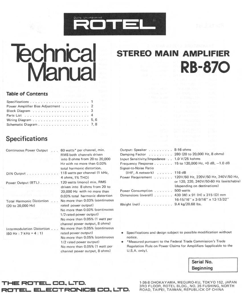
Technical
Manual

Table of Contents

Specifications ...........
Power Amplifier Bias Adjustment

Block Diagram
Parts List

Wiring Diagram ..........
Schematic Diagram ........

Specifications

Continuous Power Output

DIN Output ............

Power Output lBTLl .......

Total Harmonic Distortion
(20 to 20,000 Hz)

Intermodulation Distortion . . .
(60Hz:7kHz=4:1)

........... 1

5,6
7.8

60 watts' per channel, min.
RMS both channels driven

into 8 ohms from 20 to 20,000
Hz with no more than 0.03%
total harmonic distortion.

118 watts per channel (1 kHz,

4 ohms, 1% THD)

120 watts (mono) min. RMS
driven into 8 ohms from 20 to
20,000 Hz with no more than
0.03% total harmonic distortion
No more than 0.03% (continuous
rated power output)

No more than 0.03% (continuous
1/2 rated power output)

No more than 0.05% (1 watt per
channel power output, 8 ohms)
No more than 0.05% (continuous
rated power output)

No more than 0.05% (continuous
1/2 rated power output)

No more than 0.05% (1 watt per
channel power output, 8 ohms)

THE ROTEI- CO. LTD.

HOTEL ELECTRONICS OO.. I-TD.

STEREO MAIN AMPLIFIER

RB-87O

Output: Speaker ......... 8-16 ohms

Damping Factor ......... 280 (20 to 20,000 Hz, 8 ohms)

Input Sensitivity/Impedance 1.0 V/25 kohms

Frequency Response ....... 15 to 120,000 Hz, +0 dB, -1.0 dB

Signal-to-Noise Ratio
(IHF, A network)

Power Requirement

116 dB

120V/60 Hz, 220V/50 Hz, 240V/50 Hz,
or 120, 220, 240V/50-60 Hz (switchable)
(depending on destinations)

500 watts

430 (W) x 91 (H) x 315 (D) mm
16-15/16" x 3-9/16"x12-13/32"
Weight (net) ............ 9.4 kg/20.68 lbs.

Power Consumption .......
Dimensions (overall) .......

0 Specifications and design subject to possible modification without
notice.

0 Measured pursuant to the Federal Trade Commission's Trade
Regulation Rule on Power Claims for Amplifiers (applicable to the
U,S.Al only).

Serial No.
Beginning

1-36-8 OHOKAYAMA, MEGURO-KU, TOKYO 152, JAPAN
3RD FLOOR, ROTEL BLDG, NO. 35 FUSHING, NORTH
ROAD, TAIPEI, TAIWAN, REPUBLICK OF CHINA

Page 2

Power Amplifier Bias Adjustment

instruments: DC milli-voltmeter
Notes: Prior to Bias Adjustment, run about 5 minutes with rated output (8 ohm) and warm up Power Transistor
and Heat Sink. Set volume Control to Minimum.

Coupling
Step Adjust Adjust for
Plus Lead Minus Lead
1 T TP3 V3601 DC milli-voltmeter
2 TP2 TP4 vneoz reads 5'V-
Block Diagram
NORMAL

---- an.

SP

POWER AMP O---l
Lch

I é
: an
R n
<-J--> c
z-> L
BTL
INVERTER our Q

POWER AMP -_O_____J

PROTECTION
a
DELAY CIRCUIT

FsoI 100l
L ch ' POWER ° 9 Foal
MAIN SUPPLY F503 -c\p-< LINE
«- w-
F902
R ch POWER : c
MAIN SUPPLY F904 -
- -o\9-
1002