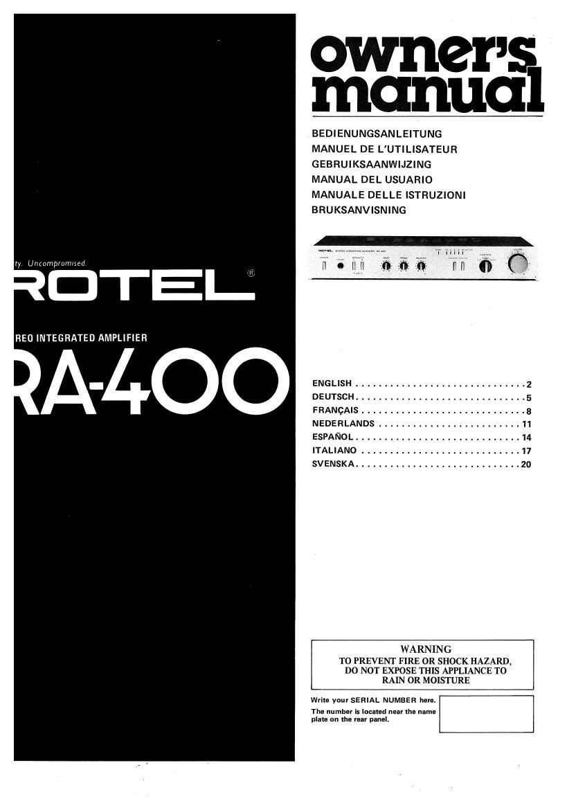
Rotel RA 400 OM

This is the 13 pages manual for Rotel RA 400 OM.
Read or download the pdf for free. If you want to contribute, please mail your pdfs to info@audioservicemanuals.com.

Page: 1 / 13
left right
Rotel RA 400 OM

Extracted text from Rotel RA 400 OM (Ocr-read)


Page 1

OW 1121s
manna

BEDIENUNGSANLEITUNG
MANUEL DE L'UTILISATEUR
GEBRUIKSAANWIJZING
MANUAL DEL USUARIO
MANUALE DELLE ISTRUZIONI
BRUKSANVISNING

ty Uncompromued

RED INTEGRATED AMPLIFIER

ENGLISH .............................. 2
DEUTSCH .............................. 5
FRANGAIS ............................. 8
NEDERLANDS ......................... 11
ESPANOL ............................. 14
ITALIANO ............................ 17
SVENSKA ............................. 20
WARNING

TO PREVENT FIRE OR SHOCK HAZARD,
DO NOT EXPOSE THIS APPLIANCE T0
RAIN OR MOISTURE

Write your SERIAL NUMBER here.

The number is located near the name
plan; on the rear panel.

Page 2

NGLISH

STEREO INTEGRATED AMPLIFIER RA-4OO

INTRODUCTION

We at Rotel want to thank you for
purchasing our audio product.

Rotel audio products are designed
to use the latest electronic techno-
logy, and they incorporate ourlong
experience as a specialist manufac~
turer of audio equipment. We are
confident that you will find satis-
faction in the high quality sound
and top performance, and that you
will find pleasure in the functional
beauty achieved through human-
engineering concept. Before start»
ing operation, please read this
instruction manual thoroughly and
acquaint yourself with the proper
mode of using the unit and all
its connections

We hope you will enjoy top-notch
performance for many years to
come.

BE FO RE ENJOYIVIENT/
POWER SUPPLY

Follow the instructions below for
maximum safety:

EXCLUSIVE NOTE FOR
U.K.

If your unit comes with a 2-
core cable without a plug, make
certain live and neutral leads
are connected to the proper
terminals. Check that the ter»
minals are screwed down firmly
and no loose strands of wire are
present.

IMPORTANT: The wires in this
mains lead are coloured in ac-
cordance with the following
code:

BLUE: NEUTRAL
BROWN: LIVE

As the colours of the wires in
the mains lead of this apparatus
may not correspond with the
coloured markings identifying
the terminals in your plug pro-
ceed as follows.

The wire which is coloured
BLUE must be connected to the
terminal which is marked with
the letter N or coloured BLUE
or BLACK. The wire which is
coloured BROWN must be con-
nected to the terminal which is
marked with the letter L or
coloured BROWN or RED.

1. Use a wall outlet for power
supply

Be sure to connect the AC line cord
directly to a household wall outlet,
and not to an auxiliary outlet on
another component. Be certain that
the outlet voltage matches the
electrical rating of the unit, found
on the rear panel name plate.

2. Connecting and removing AC
cord

Be sure to connect or disconnect
the AC line cord only after turning
off the power switch to prevent
possible shock noise or damage to
the speakers.

3. Power outlet on the rear panel
The rear panel of the unit is e-
quipped with a power supply outv
let designed exclusively for power-
ing the tuner FiT-400. Insert the
square plug of the RT-400 into the
power supply outlet. Never attempt
to insert any other plugs into this
outlet.

4. Installation

Be sure to place the unit on a level,
flat surface in a place free from hu-
midity, vibration, and high tempe-
rature and not exposed to direct
sunlight. Make sure the location

SPEAKER B

placed is well ventilated.

5. Vantilate the unit well

Never block any ventilation holes at
the top and bottom of the unit. Be
sure also to provide ample ventila~
tion space around the unit. Poor
ventilation may result in damage
due to excessive heat.

6. Do not open the cabinet

In order to avoid electric shock or
damage to the component, never
open the cabinet. If a foreign object
falls inside the unit by mistake,
turn the power off, disconnect the
wall plug, and consult a qualified
electrician or your dealer.

7. Turn the volume control initial-
ly to minimum.

When lowering the tonearm of your
turntable onto a record, an excess
of current in the lower frequency
range may cause damage to the
speakers. To prevent this, always
minimize the volume setting initial-
ly.

8. Moving the unit

When transporting, remove the AC
cord from the wall outlet and all
other connected cords on the rear
panel to prevent wire breakage and
short circuits.

9. If the unit gets wet

If the unit should get wet, immedi-
ately disconnect the AC cord, and
consult your dealer or a qualified
electrician.

10. Cleaning and maintenance

Do not use chemicals such as
benzine or thinners on the front
panel. Always use a soft, dry cloth
to clean the unit.

11. Retain the owners manual
Retain the owner's manual near the
unit, and write down the serial
number (found on the rear panel)
on the cover.

SPEAKERS

Be sure to use only speakers rated
at 4 7 16 ohms. The unit will ac-
cept two pairs of speaker systems,
but if the two systems are to be
driven at a time, each speaker
should be rated at 8 - 16 ohms.
The speaker impedance may be
found on its name plate or the
instruction manual of the speaker.

SPEAKER A

CONNECTING COMPO-
NENTS

Connect all necessary audio compo-
nents to the rear panel of the unit,
using RCA pin cordsi See the illust-
ration for properly completed con-
nections. When connecting RCA
pin cords, be sure that L (left) and
R (right) markings on each compo-
nent are matched correctly. Con-
nect the grounding wire of the turn-
table to the terminal marked GND
on the amplifier.

SWITCH ES AN D CONTROLS

(1) Power Button
Depress this button to turn on the
power. Pressing the button a second
time cuts the power.

(2) Headphone Jack

Plug your headphones into this jack
for private listening. When using
headphones, both A and B speaker
buttons should be in released
(OFF) position so that sound is
emitted only from the headphones.
Volume level of headphone sound
can be controlled with the volume
control.

(3) Speaker Buttons (A and B)
You can selectthespeakersystemls)
you wish to use by means of two
buttons. Depress button A to acti-
vate the speaker system connected
to terminals A on the rear panel.
and button B for the system con»
nected to terminals B. Depressing
both A and B buttons will activate
both speaker systems.

(4) Tone Controls (BASS/
TREBLE)

Two separate controls regulate bass
and treble, respectively: BASS is
for the low frequency range and
TREBLE for the high frequency
range. Rotate the knob clockwise
to increase the response in each

CASSETT E D ECK RD-400

PHONO TUNER AUX

TAPE MONITOR
/


TU RNTABLE

case, and counterclockwise to de-
crease it. A flat response is obtained
when both controls are set at mid
position. Effective use of controls
gives optimum sound performance.

(5) Balance Control

In the central position, sound is
produced in equal level from both
speakers, while turning it to the
right decreases the sound from the
left speaker, and turning it to the
left decreases the sound from the
right speaker.

I6) Loudness Button

This button is used when listening
at decreased volume levels, to help
overcome the human ears loss of
sensitivity to low and high frequen-


aura. EIEFEU mmnnw magnets m can I

new mums 1)

n- in

cies. Using this button boosts bass
and treble frequencies, to provide
natural sound quality.

(7) Tape Monitor Button
Depress this button to listen to the
signal from tape deck. When it is in
released position, the source select-
ed by the Function Selector (broad-
cast or record) will be heard.

I8) Function Selector

The Function Selector is used to
listen to a source other than tape
deck. Make sure the Tape Monitor
button is set in released position
when operating the Function SeIer
tor. Set the knob to TUNER to lis-
ten to broadcast, PHONO to use
turntable, and AUX for equipment

TAPE PLAYER

TUN ER FIT-400

connected to AUX terminal on the
rear panel.

(9) Volume Control

Used to regulate the volume level.
Rotate clockwise to raise the level,
and counterclockwise to lower it.
(10) Output Level Indicator
The 5 LEDs directly show the
changing power output level, from
0.5 to 25 watts.

(11) Power Indicator

Glows when the power is turned on.