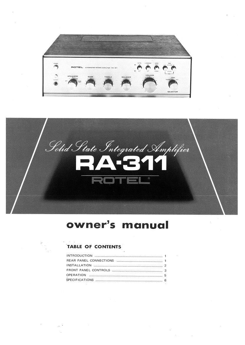
Rotel RA 311 OM

This is the 5 pages manual for Rotel RA 311 OM.
Read or download the pdf for free. If you want to contribute, please mail your pdfs to info@audioservicemanuals.com.

Page: 1 / 5
left right
Rotel RA 311 OM

Extracted text from Rotel RA 311 OM (Ocr-read)


Page 1

$4/%¢ fizz/W; JAZZ 44»;
RA'3I

owners manual

'TABLE or CONTENTS

INTRODUCTION
REAR PANEL CONNECTIONS

INSTALLATION ......................
FRONT PANEL CONTROLS ..
OPERATION IIIIIIIIIIII I.
SPECIFICATIONS . ................................ 6

01de

Page 2

We would like to take this opportunity to thank you for
purchasing our Stereo Amplifier. With the high quality
design and workmanship that goes into making this
equipment, you can be assured of its flawless performance
for many years to come. order to obtain the maximum use out of your unit, please
We have fitted every control and feature you could read the following pages of this Operating Manual
conceivably need. Designed for both versatility and ease carefully.

of operation, this piece of equipment will add professional
studio flexibility to your Hi-Fi sound center. The per-
formance is exceptional; it will allow you to experience

true high fidelity as never before. Its full and natural
stereophonic reproduction offers you musical entertain-
ment approaching that of live performances. We sincerely
hope you will treasure this professional equipment. In

Do not attempt to operate the unit until you have made
all the necessary connections.

STEREO STEREO TAPE RECORDER SPEAKERS -1
TUNER 0 LEFT RIGHT


STEREO
RECORD PLAYER
(CER)

©

:2

H AC OUTL
SWITCHED

STEREO
RECORD PLAYER
(MAG)

AC
POWER
CORD

STEREO
8-TRACK PLAYER

IJIJUIJIJ lllllllllllllllllllll°
0 00000 on

LEFT RIGHT
SPEAKERS -2

STEREO TAPE RECORDER

.Lccfl

first making sure that speakers are connected properly and
all the other necessary connections are made.

SPEAKER CONNECTlON

This unit is equipped with quick-connect jaw»snap termi-
nals for connecting two sets of speakers. Connect your
main pair of speakers to the terminals marked SPKR-l.
Ensure that your right speaker is connected to the
terminal marked 6) and that the ground (-) terminal on
the right speaker is connected to the terminal marked
Q on the extreme left of the terminal block. Similarly,
connect your left speaker between the adjacent SPKR-l
terminals marked @ and Q. If you wish to connect a
second pair of speakers, connect them to SPKR-Z termi-
nals in the manner described above.

, Caution: Ensure that the speaker leads are fastened

securely to the proper terminals, and that there are no
stray strands which may cause shorting between terminals,
If 2 sets of speakers are played simultaneously, the
impedance of each unit should not be less than 8 ohms.
Phasing:

When all connections have been made, and the unit is
operating, a check on correct speaker phasing should be
made. This is described in a later section.

RECORD PLAYER CONNECTION

The shielded cables from your stereo record player should
be terminated with RCA type phono plugs. To avoid loss
in the high frequencies, the cables should not exceed 10
feet (3 m) in length.

Connect both leads from your record player to the LEFT
and RIGHT PHONO input receptacles on the rear chassis.
If your record player has a ground cable emerging besides
two input cables, connect this ground cable to the ground
terminal post marked GND on the rear chassis.

This amplifier has two sets of PHONO input receptacles to
accommodate two record players. The MAG is suitable
for record player with regular magnetic cartridge.

The CER is for record player with ceramic cartridge.

TUNER CONNECTION

Connect the outputs of your stereo tuner to the LEFT
and RIGHT TUNER input receptacles on the rear chassis
with shielded cables. If you have another tuner, connect it
to AUX receptacles.

AUX CONNECTION

Your amplifier has two pairs of AUX input'receptacles for
use with high level program sources: tape recorder, tuner,
cassette recorder, 8-track cartridge player, TV sound or a
ceramic microphone. It should be noted that AUX is used
only for the playback purpose, and for recording see

TAPE RECORDER CONNECTION below.

When connecting a stereo tape recorder, connect both
output cables to the AUX LEFT and RIGHT input jacks
on the rear chassis, For cassette or 8-track cartridge,
similar procedure is followed, When connecting a mono-
phonic equipment, connect the single output lead to
either of the AUX LEFT or RIGHT input jack.

TAPE RECORDER CONNECTION

Terminals are supplied for connecting two tape recorders
(which incorporate playback preamplifier). Connect the
right and left output cables of the tape recorders to the
TAPE MONITOR terminals marked IN, and connect its
right and left input cables to the TAPE MONITOR
ter'minals marked OUT. If you have tape recorders with
DIN-type plugs, connect it to the REC/PB DIN sockets.

AC OUTLETS

Your amplifier is equipped with two switched AC Outlet
to provide power and switching control to whatever
component you may wish to connect to the unit.
However, the total load of equipments connected to the
AC Outlets must not exceed 200 watts.

VOLTAGE SELECTION

The amplifier is a variable voltage equipment that can run
on 100V, 117V, 220V or 240V power supply. Your unit
comes already preset at the proper voltage for use in your
area; however, if you move to an area where the power
supply voltage is different, the voltage setting can be
manually changed. BE SURE THAT YOUR UNIT IS
NOT CONNECTED TO THE POWER SOURCE BEFORE
ATTEMPTING TO MAKE THIS CHANGE.

To change the voltage setting, remove the name plate on
the rear panel and locate the VOLTAGE SELECTOR (see
figure below). Pull up the Voltage Selector plug which
has a white arrow on its top. Reinsert the Plug to the
Selector Base so that the head of the arrow lines up with
the pointer line of the voltage you desire.

#27