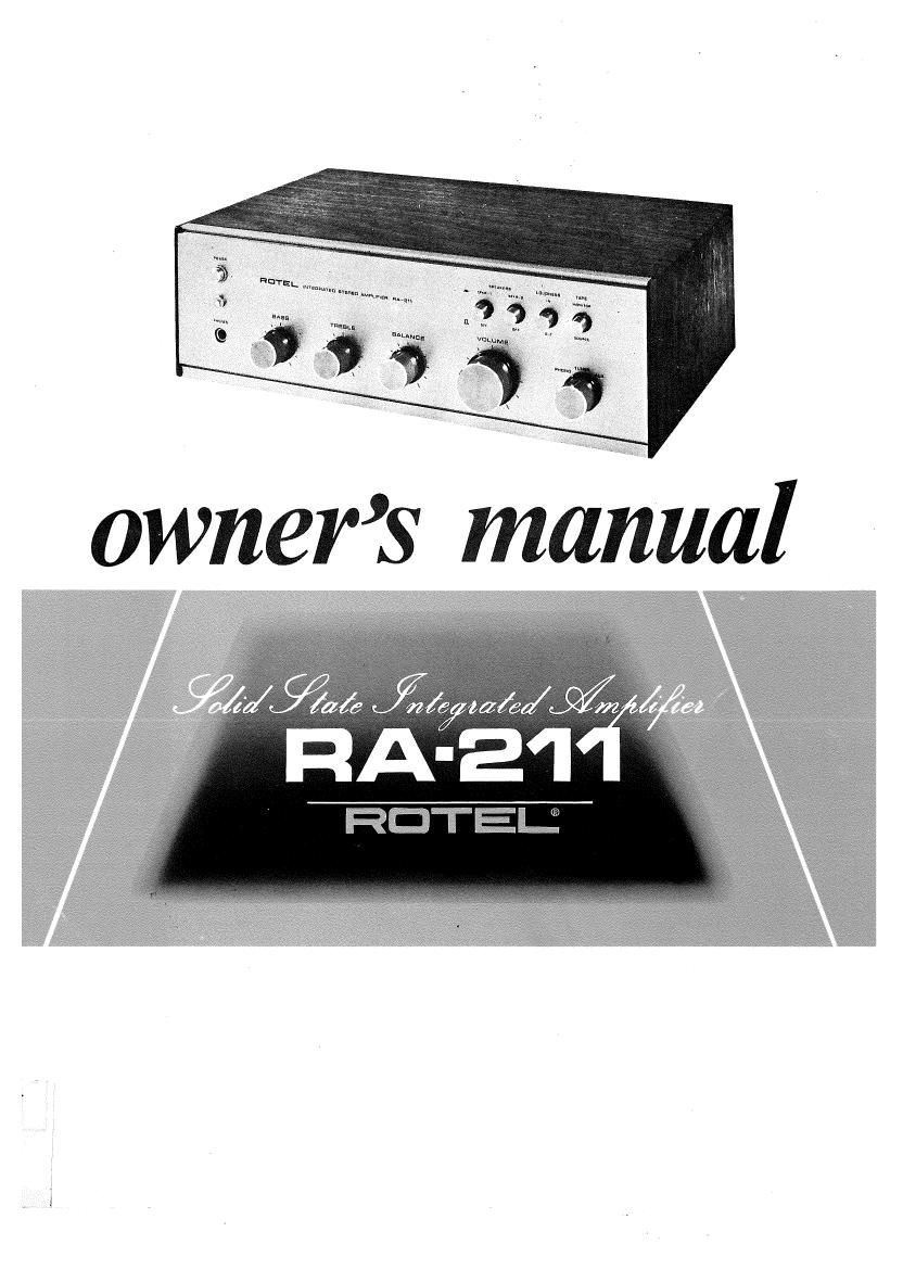
Rotel RA 211 OM

This is the 5 pages manual for Rotel RA 211 OM.
Read or download the pdf for free. If you want to contribute, please mail your pdfs to info@audioservicemanuals.com.

Page: 1 / 5
left right
Rotel RA 211 OM

Extracted text from Rotel RA 211 OM (Ocr-read)


Page 2

INTRODUCTION ~ ,. . '

We would like to take this opportunity to thank you for
purchasing our Stereo Amplifier. With the high quality
design and workmanship that goes into making this
equipment, you can be assured of its flawless performance
for many years to come.

We have fitted every control and feature you could
conceivably need. Designed for both versatility and ease
of operation, this piece of equipment will add professional
studio flexibility to your Hi»Fi sound center. The per-
formance is exceptional; it will allow you to experience

TABLE OF CONTENTS

INTRODUCTION -------------

true high fidelity as never before. Its full and natural
stereophonic reproduction offers you musical entertain-
ment approaching that of live performances. We sincerely
hope you will treasure this professional equipment. In
order to obtain the maximum use out of your unit, please
read the following pages of this Operating Manual
carefully.

Do not attempt to operate the unit until you have made
all the necessary connections.

FRONT PANEL CONTROLS -~
REAR PANEL CONNECTIONS ------------------ 3

INSTALLATION ....................................... 4
INSTRUCTION FOR CONNECTION

OPERATION ............................................. 5
INSTRUCTION FOR OPERATION """"""" 6
SPECIFICATIONS .... ................................ 6

FRONT PANEL CONTROLS * I

PILOT LAMP
The lamp lights up when the
power switch is turned on.

POWER SWITCH
A push on the button turns on the
amplifier and another push turns
it off. The reserve power outlet
on the rear panel is simultaneously
turned on and off.

SPEAKERS SWITCHES

Speaker system selector switches
for individual or simultaneous op-
eration of SPKR-l and SPKR-Z
connected to the rear panel.

BALANCE CONTROL

This knob is used to adjust the
stereophonic balance. When it is
turned clockwise the left channel
sound level is decreased and when
turned counterclockwise the right
channel sound level decreases.

LOUNDNESS SWITCH

The human ear becomes less sensi-
tive to low and high sounds when
volume level is low. With this

Wswitch turned on at low volume

settings, bass and treble notes will
be emphasized for natural listening
pleasure.

TAPE MONITOR (TAPE)

This is a monitor switch for a tape
recorder connected to the TAPE
MONITOR terminals on the rear
panel. Normally, when listening
to records or FM broadcasts the
switch is kept in the SOURCE
position.

our: sure wreanneo AMPLIFIER n l-EH

PHONES RECEPTACLE

This jack i5. used for connection of
headphones to enjoy private listen-
ing or monitoring. The speaker
switches may be turned off when
using headphones only.

BASS CONTROL

When this knob is turned clock-
wise, bass is emphasized; when
turned counterclockwise, attenu-xw
ated. With the knob set in the
center. the frequency response is
flat or normal.

i

VOLUME CONTROL

The sound level increases when

the knob is turned clockwise.When
switching on the power or the
input selector, keep it turned fully

counterclockwise at minimum.

TREBLE CONTROL

When the knob is turned clockv
wise, treble is emphasized; when
turned counterclockwise, attenu-
ated. With the knob set in the
center,the frequency response is
flat or normal.

INPUT SELECTOR CONTROL
This is used for selection of
program sources as applied to the
PHONO, TUNER and AUX termi-
nals on the rear panel.

PHONO. ..for listening to records
with a record player connected.

TUNER ...... for listening to AM/
FM broadcasts with a tuner
connected.

AUX... .for reproduction of
audio components other than
those mentioned above, which
is connected to this auxiliary
input terminal.