Rotel RA 112 OM

This is the 3 pages manual for Rotel RA 112 OM.
Read or download the pdf for free. If you want to contribute, please mail your pdfs to info@audioservicemanuals.com.

Page: 1 / 3
left right
Rotel RA 112 OM

Extracted text from Rotel RA 112 OM (Ocr-read)


Page 1

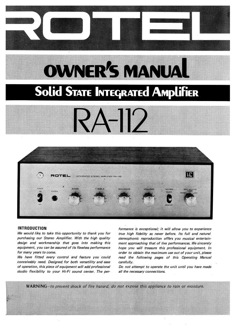
INTRODUCTION

We would like, to take this opportunity to thank you for
purchasing our Stereo Amplifier. With the high quality
design and workmanship that goes into making this
equipment, you can be assured of its flawless performance
for many years to come.

We have fitted every cantrol and feature you could
conceivably need. Designed for both versatility and ease
of operation, this piece of equipment will add profesSional
studio flexibility to your Hi-Fi sound center. The per-

formance is exceptional; it will allow you to experience
true high fidelity as never before. Its full and natural
stereophonic reproduction offers you musical entertain-
ment approaching that of live performances. We sincerely
hope you will treasure this professional equipment. In
order to obtain the maximum use out of your unit, please
read the following pages of this Operating Manual
carefully.

Do not attempt to operate dye unit until you have made
all me necessary connections.

Page 2

HOTEL.


Imcsrmrcm staring AMPLIFIFH NAME


PHONES RECEPTACLE
This jack is used for connection
of headphones to enjoy private
listening or monitoring. The
speakers will be turned off auto-
matically when using head- .
phones.


POWER SWITCH
A flip on the lever turns on the
amplifier. The reserve AC outlet
on the rear panel is simultaneous-
ly turned on and off.

PILOT LAMP
The lamp lights up when the
power switch is flipped on.

BASS CONTROL
When this knob is turned clock-
wise. bass is emphasized; when
turned counterclockwise, attenu-
ated. With the knob set in the
center, the frequency response
is flat or normal.

TREBLE CONTROL
When the knob is turned clock-
wise, treble is emphasized; when
turned counterclockwise, attenu-
ated. With the knob set in the
center, the frequency response
is flat or normal.

decreases.

I'I'IllIr

FRONT PANEL CONTROLS

IMPORTANT: Do not turn on the power switch
before completion of proper connections of the
speaker systems and inputs.

SPEAKER SYSTEMS

Speaker connection terminals are provided on the
rear panel.

The speaker system on the left (when viewed
from the front) should be connected to termi-
nals LEFT, the speaker on the right to terminals
RIGHT.

Be sure to connect the speaker cords for correct
polarity viz., the cord marked + to terminal +
and the cord marked - to terminal - . It the
polarity is reversed the phase of reproduced
sound is no longer maintained and stereophonic
presence is lost.

To make connections twist the bare strands of
the cord and screw onto the terminal post. Make
sure not to let the loose stands of the cord touch
the other terminal.

RECORD PLAYER

Model RA-112 is provided with one pair of
PHONO terminals for connection and playback
of one record player with a magnetic cartridge.
Connect RIGHT output pin jack of record player
to the RIGHT of the PHONO terminals, and
LEFT pin jack to the LEFT of the PHONO termi-
nals. The output cord from record player to be

BALANCE CONTROL
This knob is used to adjust the
stereophonic balance. When it is
turned clockwise the left chan>
nel sound level is decreased and
when turned counterclockwise
the right channel sound level

VOLUME CONTROL
The sound level increases when
the knob is turned clockwise.
When switching on the power or
the input selector, keep it turned
fully counterclockwise at mini-

vM. Mon

599 menu 3 i Am
. , I

wmn setscian
mesa


TAPE MONITOR (TAPE)

This is a monitor switch for a
tape recorder connected to the
TAPE MONITOR terminals on
the rear panel. Normally, when
listeningto records or FM broad-
casts the switch is kept in the
SOURCE position.

.INPUT SELECTOR CONTROL

This is used for selection of pro-

gram sources as applied to the

PHONO, TUNER and AUX ter-

minals on the rear panel.

PHONO......for listening to re-
cords with a record player
connected.

TUNER ...... for listening to AM/
FM broadcasts with a tuner
connected.

AUX ............ for reproduction of
audio componentspther than
those mentioned above,con-
nectedtoAUX input terminal.

STEREO RECORD PLAYER
IWITH MAGNETIC
CARTRIDGE)

STEREO TUNER

STEREO TAPE RECORDER

SPEAKERS
RIGHT LEFT

.


MAG
pHoNo-TUNER-AUX

=3
o w 00

TAPE MONITOR

OUTPUT {a l; l_. INPUT
1 I! ll

l
AC OUTLET l
vSWITCHEDfl

REAR PANEL CONNECTIONS

connected to the PHONO terminals should be as
short as possible in order to minimize loss of
high frequency characteristics. When using a
record player equipped with a ground wire, con-
nect the ground wire to the GND terminal of this
unIt.

AM/ FM TUNER

For a stereo tuner, the RIGHT and LEFT outputs
on the rear panel of the tuner should be con-
nected to the TUNER terminals on the rear panel
of this unit. Connect the RIGHT output cord
from the tuner to TUNER terminal RIGHT of
this unit, the LEFT output cord to TUNER
terminal LEFT.

CONNECTION TO THE AUX TERMI-
NALS

Output of various types of audio equipment can
be connected to the terminals, such as 8 track
tape player.

TAPE RECORDER

The TAPE MONITOR terminals on the rear panel

of this unit are for connection of tape recorder

input and output.

IN (tape playback input or connection of
tape recorder output w en playing back pre-
recorded tape through this unit.

OUT (tape recording outpUtl... for connection to
the input of a tape recorder for recording
programs from record player or tuner con-
nected to this unit.

CONNECTION TO THE GROUND (GND)
TERMINAL

When the outputs of a recorder player and a tape
recorder are connected to this unit for playback,
any ground wire from the respective equipment
should be connected to the ground terminal of
this unit provided on the rear panel in order to
prevent hum and other noises.

CONNECTION TO THE AC OUTLET
Power supply to a record player or a tuner can
be obtained from this outlet provided on the
rear panel of this unit. The outlet is turned on
and off with the operation of the power switch
on the front panel. Any equipment connected to
the outlet should not exceed the indicated power
consumption rating of 200W.

OPERATION

After all the connections have been made, turn
on the power switch.

RECORD PLAYER

1) Connect the record player output to the
PHONO terminals on the rear panel of this
unit.

2) Set the input selector switch on the front
panel to the PHONO position.

3) Make sure that the tape monitor switch is in
the SOURCE position.

4) Turn the other control knobs to obtain the
sound level desired.

AM/FM TUNER

1) Connect the tuner output to the TUNER
terminals on the rear panel of this unit.

2) Set the input selector switch on the front
panel to the TUNER position.

3) Make sure that the tape monitor switch is in

the SOURCE position.

Turn the other control knobs to obtain the

desired level after the tuner has been tuned in

to the desired station.

4

TAPE RECORDER

Connect the tape recorder input and output to
the TAPE MONITOR terminals on the rear panel
of this unit. ,.

RECORDING-

1) Make sure that the tape monitor switch on
the front panel is set in the SOURCE position.

2) Set the input selector switch to one of the

program source positions, PHONO, TUNER

or AUX.

Perform recording operation of the tape re-

corderto record the desired program source

through this unit.

3

PLAYBACK

1) Press the tape monitor switch and set it in
the MONITOR position. (In the case of play-
back, the input selector switch can be kept in
any position as it is overridden at this opera-
tion I

2) Perform a playback operation of the tape
recorder and control the other controls on

this unit to enjoy tape playback at the desired
sound level.

STEREO HEADPHONES
Just insert the PHONES jack to enjoy private
listening.

TONE CONTROLS

BASS ...... for control of bass notes.

TREBLE ...... for control of treble notes.

Even when the tone controls are set in the center
position, it is not always possible to obtain an
acoustically flat response depending on program
sources and acoustic characteristics of the
listening room. The tone controls enable the
listener to have an acoustically flat response.
However, an excessive.boost of bass or treble
notes may produce unpleasant results, so the
tone controls should be used only to compensate
for acoustic requirements.

INSTRUCTION FOR OPER TlON

LOCATION OF OPERATION

Model RA-112 is designed with due considera-
tions for heat radiation.

However, it should not be installed in an airtight
cabinet or exposed near heat sources.

CONNECTION 0F SPEAKERS
The FIA-112 amplifier is specified at the load
impedance of 8-16 ohms. Most speakers are

rated at 8 ohms.

If used at below 8 ohms, this unit may burn out
or give rise to mal~functioning of this unit when
used continuously for considerable time. So, do
not use speakers rated below 8 ohms.

HUM AND NOISE

In any high fidelity installation, hum may be
caused by the interconnection of a record player,
tuner and amplifier, as a result of the cables and
different grounds. If hum is experienced with
your amplifier, disconnect everything but the
speakers from the unit. If hum persists, reverse
the AC line cord. Plug in the record player and
if hum appears, reverse the record player power
plug and connect a single lead from the record
player chassis to the ground post On the rear
chassis. Connect your other devices in this
manner.

Caution: Hum may also be induced by defective
connecting cables or by running these cables too
close to a strong AC field.