ROLAND SH 5

This is the 54 pages manual for ROLAND SH 5.
Read or download the pdf for free. If you want to contribute, please mail your pdfs to info@audioservicemanuals.com.

Page: 1 / 54
left right
ROLAND SH 5

Extracted text from ROLAND SH 5 (Ocr-read)


Page 1

i 1976-10-30 SI-l-5
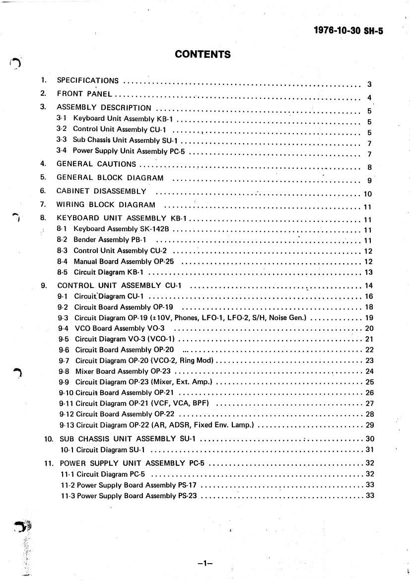
.. CONTENTS
I)

1. SPECIFICATIONS ...... l .................... . .................. 3
FRONT PANEL .................... , ................................ 4
3. ASSEMBLY DESCRIPTION ................................................. 5'

31 KeyboardUnitAssemblyKB-l ................. 5

3-2 Control Unit Assembly CU-1 ....... . ..................................... 5

3-3 Sub Chassis Unit Assembly SU-1 .................................. ' .......... 7

3-4 Power Supply Unit Assembly PC-5 . . . . ...................................... 7

4. GENERALCAUTIONS....:........., ................................. . ..... 8

5. GENERAL BLOCK DIAGRAM .............................................. 9

6. CABINET DISASSEMBLY ......................... ......................... 10

7. WIRING BLOCK DIAGRAM ..................................... 11

'5; 8. KEYBOARD UNIT ASSEMBLY KB-1 .......................................... 11
8-1 Keyboard Assembly SK-1428 .............................................. 11

8-2 Bender Assembly PB-1 ............................... . . . .. ........... . . . . 11

8-3 Control Unit Assembly CU-2 ...... '. ....................................... 12

8-4 Manual Board Assembly 0P-25 ............................................ 12

85 Circuit Diagram KB-l ...... . ..................... > ..... . . . . . . . . . .. ........ 13

9. CONTROLUNITASSEMBLYCU-l ........ 14

9-1 Circuithiagram CU-l ............ . . . . . . . . . . .............................. 16

9-2 Circuit Board Assembly 0P-19 ............................................ 18

9-3 Circuit Diagram OP-19 (110V, Phones, LFO-l, LFO-2, S/H, Noise Gen.) ............. 19

9-4 VCO Board Assembly VO-3 .............................................. 20

9-5 Circuit Diagram VO-3 (VCO-i) ............................ . ................ 21

9-6 Circuit Board Assembly OP-2O ............................................. 22

9-7 Circuit Diagram OP20 (VCO-2, Ring Mod) .................................... 23

'1 98 Mixer Board Assembly OP-23 ....................................... . ....... 2 4
' 9-9 Circuit Diagram 0P-23 (Mixer, Ext. Amp.) .................................... 25
9-10 Circuit Board Assembly OP-21 ............................................. 26

9-11 Circuit Diagram 0P-21 (VCF, VCA, BPF) .................................... 27

9-12 Circuit Board Assembly OP~22 ............................................. 28

9-13 Circuit Diagram 0P-22 (AR, ADSR, Fixed Env. Lamp.) .......................... 29

10. SUB CHASSIS UNIT ASSEMBLY SU-1 .............. 30

104 Circuit Diagram SU-1 .................................................... 31

11. POWER SUPPLY UNIT ASSEMBLY PC-5 ..................... . ................ 32

11~1 Circuit Diagram PC-S .................................................... 32

11-2 Power Supply Board Assembly PS-17 . . . . . . . . . . . . . . . . . . .7 .................... 33

11-3 Power Supply Board Assembly PS~23 ......... V ............................... 33

Page 2

1976-10-30 SH-5 '
Y
12. ADJUSTMENT ............................................................ 34.
12-1PS-17,PS-23 .......................................... '- ................ 34 (
12-1-1 +14v,-14v ................................ ' ...................... 3 4
12-2 OP-19 .................. : ............................................. 34
12-2-1 +1ov,-1ov ....... ; ............ ................... ) ................ 34
122-2 LFQ-1..... ..... g ........... ......... 34
12-2-3 SAMPLE 81 HOLD '. ........... L ..................................... 35
12-2-4 NOISE, GENERATOR .............................................. 36
12-3 KB-1 ................. .... ........................................... 36
12-3-1 KEY VOLTAGE ...... , .......................................... '...35
12-32 BENDER VOLTAGE ................................................ 37
12-4 vo-3 ...... ................................ a .................... 37
124-1 vco RANGE SET ................................................ 37
12-4-2 vco-1 .......................................................... 37
1243 vco-1 ............ 38
124.4 vco-1 FREQUENCY WIDTH ........................................ 38
12-45 vco-1 FREQUENCY ADJUSTMENT .................................. 41.
12-50P-20 ........................................................... 41
_ 12-5-1 vco-2' ............................................................ 41
125-2 vco-2 ............................................................ 41
12-53 vco-2 FREQUENCY WIDTH .............................. =3 ......... 42 »
12-5-4 vco-2 FREQUENCY ADJUSTMENT ........................... ' ....... 4 2
12-5-5 RING MOD ...................................................... 43
12-6 OP-21 . . .- ........................................................... 44
126-1 VCA ............................................................ 44
12-52 VCF ............................................................ 45
12-7 OP-22 ............................................................. -... 48 1
12-7-1 ADSR ............................................................ 48
13. PARTS LIST .............................................................. 49
13101125 ................................................................ 49
132 0P-19 .......................................... : ...................... 4 9
133v03 ......... so
13-4 OP~20 .......................... . . .................................... 51
13-5 OP-23 ................................................................ 52
1360P-21 ..................... . ..................................... 52
137 0P-22 ................................................................ 53
13-8 PS-17 ................................................................ 53
139 P523 ......... , ....................................................... 54-
-2-

Page 8

1976-10-30 SH-5

4. GENERAL CAUTIONS

4-1. Fuses .
When replacing fuses, use only those rated as shown on the caution label on the circuit boards

Repeatedly blown fuses indfate something wrong with the circuits. Using larger value fuses will only aggravate
this condition and will result in damage to the clrcuits.

4-2. Adjustment
Calibration adjustments should be done in the order given.

Accurate adjustment can be assured only if the procedures are followed exactly as given.

43. Slide Switch '

Double check the positions of slide switches. I

Slide switches set in between positions is the largest cause of malfunction of this synthesizer.

44. Replacement of parts
Use only those as specified in the Parts List.

Use of parts other than as specified can cause function instability or circuit damage.