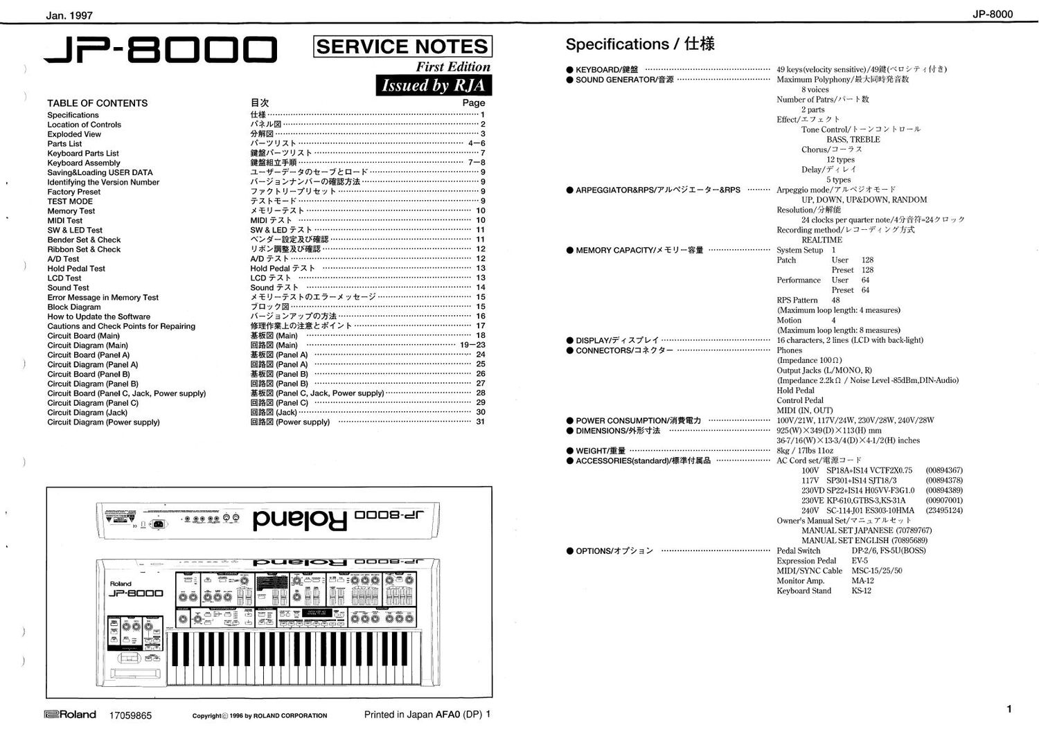
ROLAND JP 8000

This is the 31 pages manual for ROLAND JP 8000.
Read or download the pdf for free. If you want to contribute, please mail your pdfs to info@audioservicemanuals.com.

Page: 1 / 31
left right
ROLAND JP 8000

Extracted text from ROLAND JP 8000 (Ocr-read)


Page 1

ERoland 17059865

Copyright©1996 by ROLAND CORPORATION

Printed in Japan AFAO (DP) 1


Jan. 1997 JP-8000
I F _ B D D D SERVICE NOTES SpeCIficatIons / iifi
) Flrst Edltlon . KEYBOARD/figs ................................................ 49 keys(velocity sensitiveflzlgflé (\° U 7 7" 4 (1' E)
V . SOUND GENERATOR/£71? """"""""""""""""""" Maximum Polyphony/fijililfldafififi
W Issued by RJA 8mm
' TABLE OF CONTENTS E :5: Page Numb: diam/T W
Specifications iflfi """""""""" ~ 1 pa 5
Location of Controls Iffilblfl - 2 EfieCt/l 7 I 7 b \ \
Exploded View aging .. 3 Tone Control/ r - / I! / l~ U -)1«
Parts List /\°-/ U z |~ - 4-5 BASS, TREBLE
Keyboard Parts List fifi/t-y U x l~ 7 Chorus/3' ' 3 2
Keyboard Assembly figfirfifiliEf-IE .............................. 7-8 12 types
Saving&Loading USER DATA :L-if-vi- 7 oat - 7: El - F -~ 9 Delay/? 4 V 4
Identifying the Version Number I\' - 7 a 7" / I) - means 9 5 types
Factory Preset 7 7 7 I» U ~7° U 12 y l~ -- 9 O ARPEGGIATOR&RPS/7)b\°7l - 9 -&FlPS ~~~~~~~~~ Arpeggio mode/7 )L\° 971 4:- - F
TEST MODE 5'1 1 45- IC 9 UP, DOWN, UP&DOWN, RANDOM
Memory Test X 'T: U -7-1 l~ ~ 10 Resoludon/fiffiéfi
MIDI Test MIDI 37 1 |~ 10 24 clocks per quarter note/4fi%fi=247 E v 7
SW & LED Test SW & LED 31 l~ ~ ~ 11 Recording method/ 1/ I! H 7: 4 7 775K
Bender Set & Check «v a ~E§EKU§E§E~ ' 11 REALTIME
Ribbon Set & Check U $>fififilfi§fi§§ ' 12 . MEMORY CAPACITY/X :E U _g§ ........................ System Setup 1
\ N D Test N D 71} l ': """" Patch User 128
/ Hold Pedal Test Hold Pedal TX I Preset 128
LCD Test LCD 73 1 ''''' Performance User 64
Sound Test Sound 72 l~ Preset 64
Error Message in MemoryTest (EU-51 rmlfi-X ylz--/ 15 RPS Pattern 48
BIOCK Diagram 7 El 7 7E ............ 15 (Maximum loop length 4 measures)
How to Update the Software /\'- 7 3 >7 7 777371315 16 M tion 4
Cautions and Check Points for Repairing egresiossgt :fitf > l~ (Janum 100p length 8 measures)
3:3: gatgya'gin) 351213212) 0 DISPLAY/7" r x 7" y 1 ~~~~~~~ 16 characters, 2 lines (LCD with back-light)
Circuit Board (Panel A) fili- (Panel A) ~ . CONNECTORS/37 7 9 _ """""""" Phones
,1 Circuit Diagram (Panel A) EKE (Panel A) (Impedance 1000)
Circuit Board (Panel B) £15 El (Panel B) Output JaCkS (L/MONO, R)
Circuit Diagram (Panel B) |§Ii§l (Panel B) ............ (Impedance 2.2k0 / Noise Level -85dBm,DIN-Audio)
Circuit Board (Panel C, Jack, Power supply) £115?- (Panel 0, Jack Power supply) H01d Pedal
Circuit Diagram (Panel C) IEIPGE (Panel C) ~~ ~ Comm] Pedal
Circuit Diagram (Jack) IEIPEI (Jack) .......... MIDI (IN, OUT)
Circuit Diagram (Power supply) Ifilflfim (Power supply) 0 POWER CONSUMPTION/iiiifijl 100V/21W, 117V/24W, 230V/28W, 240V/28W
. DIMENS|ONS/5Hl37.l'5£ ' 925(W) X 349 (D) X 113 (H) mm
36-7/16(W) >< 13-3/4 (D) ><4-1/2(H) inches
. WEIGHT/E; ....................................... 8kg / 171135 1102
) . ACCESSORIES(standard)/E N'Enr': AC Cord set/ $11,133 - F
100V SP18A+ISI4 VCTF2X0.75 (00894367)
117V SP301+ISI4 SJT18/ 3 (00894378)
230VD SP22+1514 H05VV-F3G10 (00894389)
1 230VE KP-610,GTBS-3,KS-31A (00907001)
1 240V 50114101 ES303-10HMA (23495124)
( Ovtmers Manual Set/V L :L 7» t ~y |~
MANUAL SET JAPANESE (70789767)
MANUAL SET ENGLISH (70895689)
. OPTIONS/j- 79 a / .......................................... Pedal Switch DP2/6, FS5U(BOSS)
Expression Pedal EV-5
MIDI/SYNC Cable MSC-l5/25/50
Monitor Amp. MA-12
Keyboard Stand K512
)
1

Page 4

J P-8000

PansIJst/l

I-VUXF

SAFETV PRECAUTIONS:
m pansmarkod A hnymmy
related cllalaclcmucs
Use only listed parts for
replacement

32:77:33:
A fllffmfwbfilinnula. £2
Lfigllixfiififv< Blvd;
more
iifimlfiu. REE; (7
3%, ififiétttglmnE? 5'1
®§K§l$fibthlx5ll L1

CONSIDERATIONS ON PARTS ORDERING
When omnng any pans Ilslen in the pans 1m, please specify the following nuns m the order sheet,

QTY PART NUMBER DESCRIPTION MODEL NUMBER
Ex, 10 22575241 Sharp key 020/50
15 2u7ol7aoo Knob (orange) DAC- 1 51)

lehne to completely ml lhc above llems wnln correct number and descnpllon will Nsull in delayed or wen
und end replacement.

/\'- Rlzfltasfiu
a, are/7 r 1:11» lbfrgamlfia mains LTT amt (1519111171? 0
Zfifi /\'-7+//<~ 58 1mm:
91) to 225752; Sharp key 020/50
15 2247017300 Knob (orange) DAG-15D

I: LiEAHAiL fiiigrfifiéiifit EE§K§MY5§§T§ and: l , Alfifiifihwlfilflllx 9 $

JACK,SOCKET/7 -\7 7 7 JJ y l~

Jan. 1997

13429825 YKF51~5054 MIDI Socket 1K1 on JK

13449283 HLJ7101-01-3010 Mono JK3-5 on JK

13449284 HLJ7001-01-3010 Stereo JK2,6 on JK
DISPLAY UNIT/$7111: v l~

00127378 RCM7044Uv1A LCD Unit

Féwa

1s lflllfihifilrfihrL§To

> Main Board

Panel board A PB

Panel board C JK

Power Supply board JP
BB ===> Bridge Board 13

=-=> Panel board B
JacK board
- - JumPerboard
=> Inlet Board

NOTE . The parts marked # ale nevi/(initial parts).
if E: #fiiifdbtB/Kulllit $035???)

CASING/1' - X

# 01019801 TOP CASE

# 01121390 BOTTOM BOARD

# 01 121401 DISPLAY COVER
12359105 RS-09 FOOT W 235-105

CHASSIS/9 1 - 9

# 01121489 PWR SPLY HOLDER
# 01128312 INSULATING SHEET
40126812 CAUTION LABEL BARRIER
NOTE : When ordering 01 121489, be sure to order 01128312 and 40126812 along with it. (Refer to Cautions and
Check Points during Repair")

31 7e :0112148923E1O1filit mozooetnweercaxrmxo
( Flaalraimzea 7K4 y H Essex 752:ny )

KNOB,BUTI'ON/) i 7% \ 7.1557 /

1 2499 1 75
0023 1 40 1
22485 1 87
00900 1 89
00900 1 90
22495274
22495277
22495 27 8
22495 279

SWITCH/X f 7 5

G S-BUTTON SIH BLK

U R-KNOB MF270 BLK/LCG
A S-KNOB M BLK/LCG

D S»KEYTOP SXIH BLK

D S-KEYTOP SX2H BLK

D S-KEYTOP MX1H BLK

D S-KEYTOP MD1H BLK

D S-KEYTOP MD2H BLK

D S-KEYTOP MD3H BLK

Power Switch
Rotary VR
Slide VR
small

small, double

with lens
with lens, double
with lens, triple

13169752
A 13129160

EVQ 213 05R
SDDBLl-B-D-Z TV-5

on Panel boards
SW301 on IE

BENDER UNIT/\M/ §_1: 7 1
70564101 PB-HOZOI BENDER TURBOLESS
NOTE : The BENDER should be replaced as an entire unit Individual (discrete) parts cannot be replaced.
ii E :Nx 57-22441; 1: 7 tilfiofio r < fiéwo
Bblfiufiilfiffliéifilif 3 ifilvo

KEYBOARD/fifia'rélilifib
# 70895767 519949.]; KBD ASSY
NOTE :See 'SK-949-B PARTS LIST' for details.
5: 7e $151411; HEB/w 7 l) x lSK-949~BJ 255,16. LT < fie we

PCB ASSY/Efia'TEfiltfl

#I70890112 MAIN BOARD ASSY

# 70890134 PANEL BOARD A ASSY
# 70890145 PANEL BOARD B ASSY
# 70894889 PANEL BOARD C ASSY
# 70894923 JACK BOARD ASSY

# 70894901 PS+JP BOARD ASSY

# 70894912 INLET BOARD ASSY

NOTE1 : The lithium battery mounted on the MAIN BOARD ASSY is not used for storing of data preset at the
factory, Please note that even if the main board is ordered, it will not come mounted with the lithium battery.

NOTE2 : The replacement PS+JP BOARD ASSY consists Of the following PCBs.

NOTE3 : The long leads on the LEDs mounted on the panel board tend to bend easily so take adequate precautions
when replacing the board.

5: E1 : MAIN BOARD ASSY REE a has 2:) I) r 9/ 2am; rainwater»?- & Elfiéfire E 114717
lifilfi éiLCwid/Vo MAIN BOARD ASSY )2 7r- 5?- L1 0 e U +7AEM11E§$ firm
i dAOCK SHEET B 0

5: E2: TRIP/£113 PS+JP BOARD ASSY lit HTOEJEVP 513i 1) i To
~ POWER SUPPLY BOARD
JUMPER BOARD
BRIDGE BOARD

51 fis:1t$)v*- FLOLEDIL E75§E< 11137330 rrvmo fi- Ffifiwfililfie. LT < ff is we

10
01016123 HD6413002FP16 CPU ICl on MB
# 01231701 28F400BV-B60 Flash 1C2 on MB
00129278 SSC1080FOB Custom IC19 on MB
00892556 TC170C140AF-003 Custom IC6-9 on MB
# 01120523 HM514800CJ6Z DRAM ICl2 on MB
# 01126612 TC514260DJS-60 DRAM ICIO on MB
# 01127356 HM628128ALFP-7 SRAM IC3.4 on MB