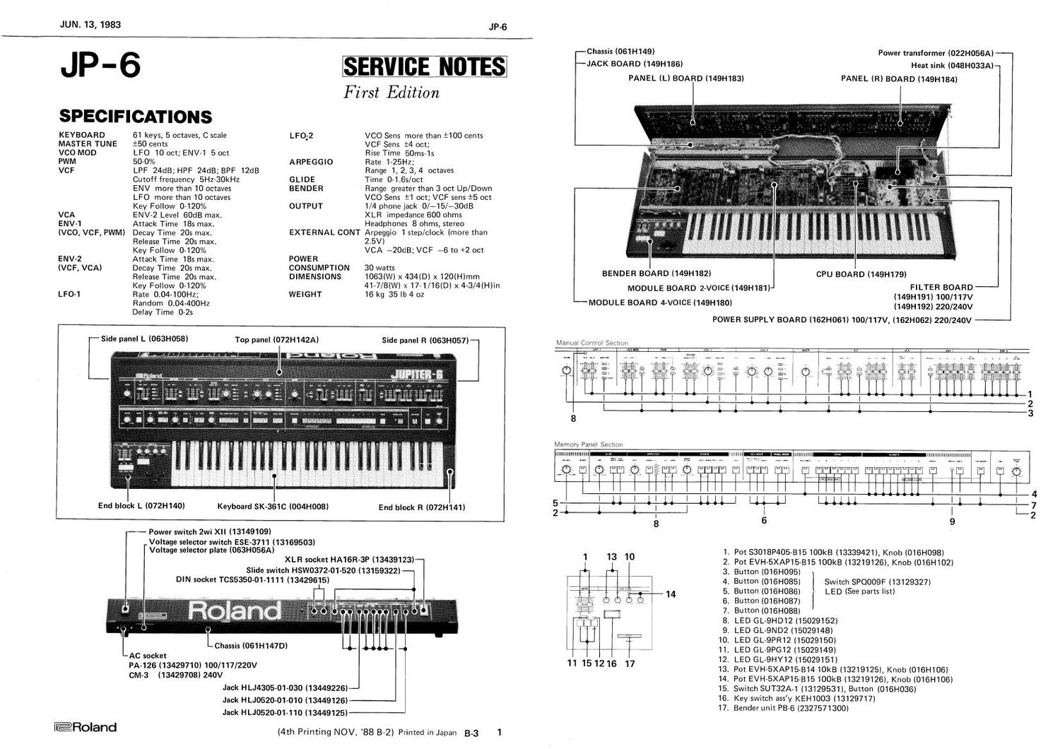
ROLAND JP 6

This is the 27 pages manual for ROLAND JP 6.
Read or download the pdf for free. If you want to contribute, please mail your pdfs to info@audioservicemanuals.com.

Page: 1 / 27
left right
ROLAND JP 6

Extracted text from ROLAND JP 6 (Ocr-read)


Page 2

JP-6

JUNE 13,1983

CIRCUIT DESCRIPTION

General
1024
PANELBOARD _ I RAM :
r po1's I I 1013
l A
' O :J: 1i /D l 1012
I
l SWs . LEDs 8031
.= i /
: .=, | I 8051 - - - '
' |
l._ _ _ _ _ _ ___l MASTER
CPU
KEYBOARD _ _ _ _
CPU BOARD

JAck BOARD '

The setting values of the potentiometers on the PANEL
BOARDs are converted into digital equivalent by the
A/D converter (IC13) on the CPU BOARD, and are read
by the MASTER CPU (1012). The setting values of the
switchies on the PANEL BOARDs are directly read by
the CPU through the Matrix circuits divided into the two
PANEL BOARDs. The CPU (1012) writes these data
into RAM (IC24). The data in the RAM are read by
control operation through the panel when required and

MASTER CPU

1612 (CPU BOARD) P8031/P8051/P8051-318

Difference Between CPUs

P8031 ........... for early products, associated with
PROM ICZG containing the opera-
tional program exclusive to the

JP-6.

P8051 ........... tentatively used. To be handled as
P8031.

P80513318 ........ contains the program in the on-
chip ROM, making IC26 redun-
dant.

Compatibility

Three CPUs function the same as long as external
PROM lC26 is enabled. Pulling up EA (pin 31) of
P8051-318 will change programs from external to
internal (see CPU circuit diagram), but this is unneces-
sary when IC26 operates perfectly.

2

are fed to the CPUs (SLAVE CPUs) on the MODULE
BOARDS in serial format.

The SLAVE CPUs control VCOs, VCFs and VCAs using
the data (tone data, keyboard information, etc.) coming
from the MASTER CPU.

The BENDER and foot pedal controls are processed by
analog circuits. The SLAVE CPUs gate the right analog
switches to pass these control voltages to individual
destinations to introduce additional features.

Isr/vvn
vss vcc ¢

l l l l l l l l

180:"

may »

roan

§
Hillllllllllllillllllll
llllllli

nous. nus

Logic Symbol

Pin Configuration

rIsouEch
nmnzm commas

--+ - H-

me mm
"W m we 11:35:13.

own new

mm "33" am new)" commas

l I
l i
| l
| 1
:fi it i

|
| l
| l
i l
| l

nos.

"111T

macnmmats
m ms nus sum ow

E53135; commune no 5%: W"
¥v5éuno~om
luvs-nuns mm
L- V 7 3-33-11 1
mmum coanoL "nun. veins 3:... SERVAL

nobles: mu nus.
ms nu ems

Block Diagram

RSTH The level of the reset terminal is kept
high by RESET circuit (TR6, TR7, TR8
and lC21l for more than 24 clocks after
the DC voltages becomes stable.

5V
0
approx approx
20ms JABOHIS
r e
power on
P0 --------------- carries data and address data.
ALE ~~~~~~~~~~~~ sends latch clock to IC17 to latch
address off the P0 bus.
PSEN --------- enables |CZ6 to read a program in the
PROM through the P0 bus.
P1~~~ serves as an I/O port.

it presents panel LED lighting, potentio-
meter and switch reading addresses.
P2 issues addresses

fifi ~~~~~~~~~~~~~ enables Read Address Decoder |C19
when the CPU wants to read necessary
data. |C19 decodes select signals (P2.4~
P2.6) and directs either of 1013, lC14,

ICZB, IC24, IC25 or IC27 to place data
on the data bus.

Wfi --------------- enables Write Address Decoder lC18
which, upon decoding address being fed,
clocks RAMs, A/D converter 013) and
LED driver 015, IC16).

T0, T1, TX ------ transmit data to the cassette tape inter-
face, MlDl bus and SLAVE CPUs.

~- reads data from MIDI bus.
. reads data from the cassette interface.
.. not used.

run

iii!

roan man-nu.

Program/Memory Read Cycle Timing

SLAVE CPU

|06 (MODULE BOARD)

Compatibility --In the same way as 1012 on the CPU
BOARD, P8031, P8051 or P8051819
is used for the CPU (106). Refer to
"MASTER CPUC P8051-319 makes 101
and lC5 redundant.

Rs1'............ receives a shaped reset pulse from the
CPU BOARD through buffers. The
buffers (103) and capacitors (C5 and
C7) effectively protect the CPU against
static charge.

I

J

P0, P2, PSEN-~~-Refer to the description in the

and ALE MASTER CPU section.
P1 ~~~~~~~~~~~~~~~ delivers addresses to the S/H analog
switches.

Ft-Dancl INT 14 clock the address latches (IC7, ICS) to
ON or OFF analog switches.

INT 0 ~~~~~~~~~~~ reads the frequencies of the V005
during computune operation.

RX ------------ accepts data from the MASTER CPU.

TXnm~~~mmgoes high during Computune, signaling
MASTER CPU not to send data.

T0, T1 ~~~~~~~~ transmit LFO-LED lighting signals, and

transmit and receive LFO sync pulses to
and from the other SLAVE CPU.