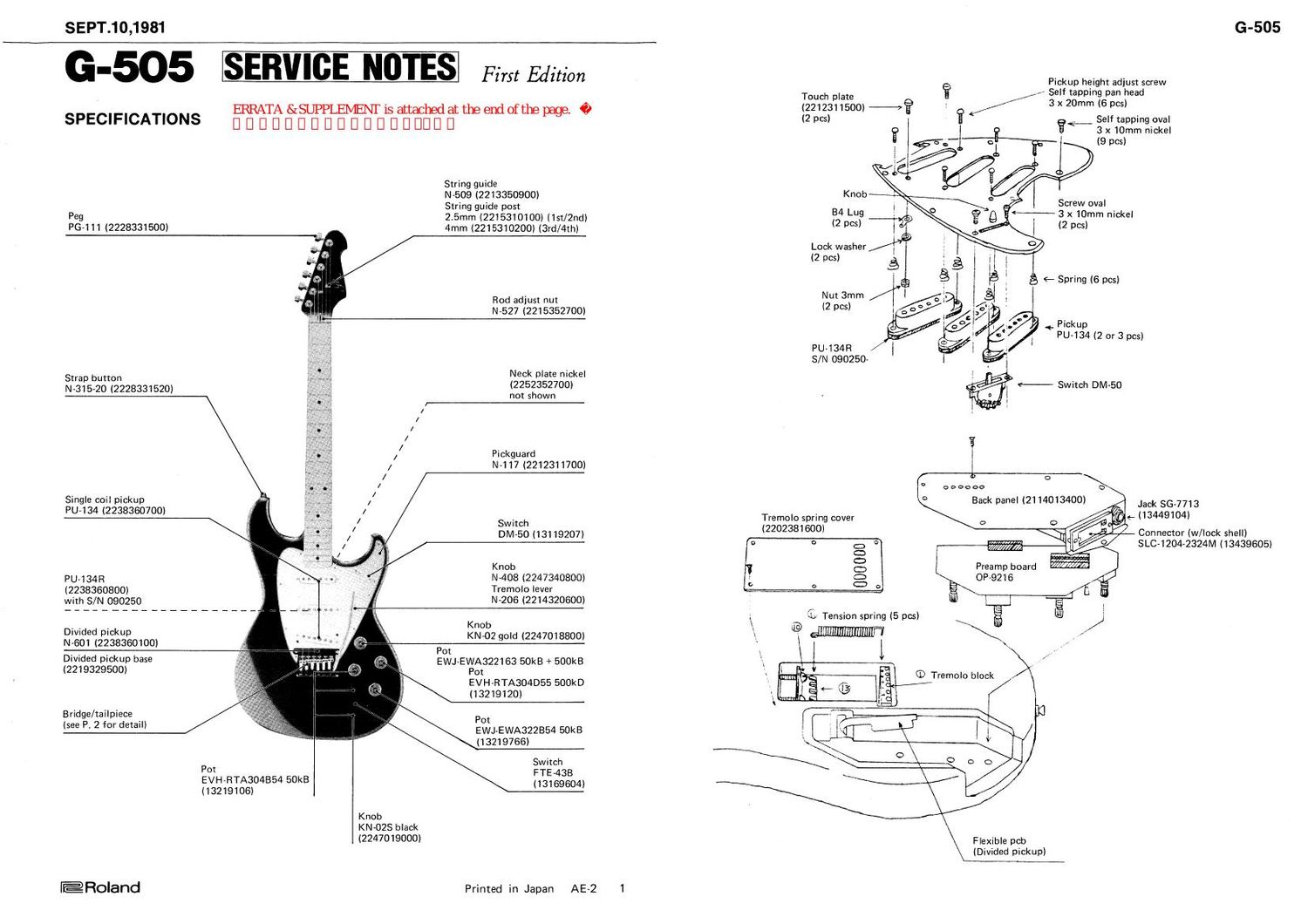
ROLAND G 505

This is the 6 pages manual for ROLAND G 505.
Read or download the pdf for free. If you want to contribute, please mail your pdfs to info@audioservicemanuals.com.

Page: 1 / 6
left right
ROLAND G 505

Extracted text from ROLAND G 505 (Ocr-read)


Page 2

G-505 SEPT.10,1981

BRIDGE/TAILPIECE (TREMOLO ASSEMBLY)

On the guitar with tremolo mechanism, balance of tension on the guitar strings and
tremolo springs ® determines strings height and length when tremolo lever (3) rests at
neutral. Thus, to achieve satisfactory tuning action, understanding of tremolo mechanism
and its installation is necessary before starting tuning.

The tailpiece pivots on wood screws ® , cylindrical travel range being limited by points
@ and ©.

Six screws serve as fulcrum as well as anchor for tailpiece mounting plate. Their
insertion angle and tightness are key to a stable and smooth actions Screws must be
perpendicular to the mounting plate and there should be no clearance between their
faces. The entire bottom of mounting plate must be flush with guitar top (Fig. 3-a ®l
when all strings are relaxed.

Fig. 3-b Unsettled plate will jolt with lever traveling.

Fig. 3-d Overtightened, the plate resists lever motion.

NOTES: ,

When replacing tremolo assembly or rescrewing all the screws ® , screw in the following
order - #1, #6, #2, #3, #4 and #5. As for factory assembly, the number of tremolo
springs is five and may be changed to four or three to meet the users preference.

TUNING. STRING HEIGHT. STRING LENGTH

Both adjustments must be done after conformation of tailpiece setting to the conditions
in the preceeding section; and be repeated for a successful result since any tension change
on one string will alter the pitch of the remaining strings. This is due to balance point
shift, e.g. if a string is wound to raise the pitch, the tailpiece and bridge unit is pulled
toward the guitar neck. Five strings slacken and their pitch lower.

Fig. 1

Tremolo block (2213334100)
Bridge base plate (2213334000)
Tremolo lever (2214320600)
Bridge saddle 21 mm chrome (2213390500)
#1, #2, # 3
Bridge saddle 19mm chrome (2213390600)
#4, #5, #6 Fig. 2
6 Height adjust screw (worm)
3x8mm . . .. #l,#6
3x 10mm . . . #2-#5
7 Saddle spring
8 Intonation adjust screw /
3 x 20mm pan b / 5/
9 Screw 4 x 10mm flat .y.._
10 Wood screw 3.6 x 30mm round i.- WJ] w E] _ '
11 Tension spring (2217330600) a c d
12 Tension adiust screw 5 x 50mm _
round self tapping F'g- 3
13 Tension spring bracket (2219329600)

awn--

U1