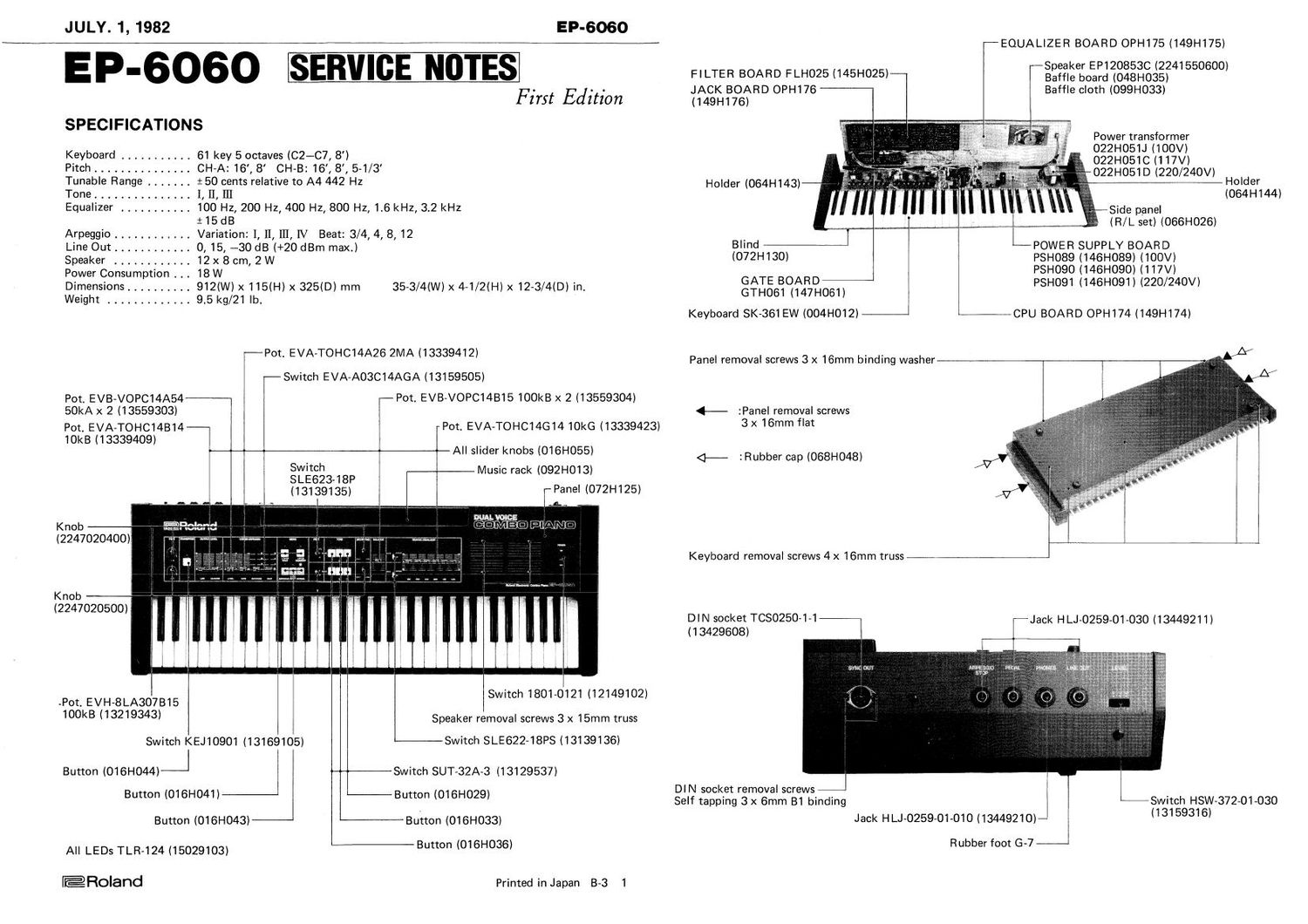
ROLAND EP 6060

This is the 10 pages manual for ROLAND EP 6060.
Read or download the pdf for free. If you want to contribute, please mail your pdfs to info@audioservicemanuals.com.

Page: 1 / 10
left right
ROLAND EP 6060

Extracted text from ROLAND EP 6060 (Ocr-read)


Page 2

EP-GOGO
CIRCUIT DESCRIPTION

TONE GENERATORS

The Tone Generators consist of Master Oscillators 01-03, 04-06
(Gate Board), Footage Selectors ICI-IC3, IC4-ICG (Fiilter Board)
and Groups of programmable Counters IC1-ICS, lC4-IC6 (Gate
Board).

01-03, 04-06 MASTER OSCILLATORS -GATE BOARD-

Two master oscillators are the same in circuit configuration, but
04-06 oscillates at higher frequency than 01-03 to provide 5-1/3
pitch for CH-B. Both ocsillators can be detuned by up to 50 cents
high or low with TUNE control. These high frequency signals are
routed to sets of programmable counters through Footage Selectors.

lC1-IC6 PROGRAMMABLE COUNTERS -GATE BOARD-

The programmable counters are each capable of dividing input signal
(from master oscillator via footage selector) by n (divisor) applied
on the D pins. When a key is played on the keyboard, CPU knows
the note to be produced, through scanning matrix (DB-Decoder
ICS-Key [and TRANSPOSE] contact- Inverters ICZ, IC4-Port 1), and
outputs divisor data on DB lines. At the same time CPU places
address code (programmable counter chip select and counter select)
on Port 2. With this code a counter is selected among 18 counters
(three on each chip, two of them are not used) and supplies audio
signal for that key to a Tone Gate to which Gate Signal is concurrent-
ly applied from GATE LATCH I06 or IC7.

TONE GATES -GATE BOARD-

The following descriptions assume a tone gate in CH-A is to be
assigned to a key pressed since all the gates function in the same
way.

Upon key pressing one of output pins of Latch |C6 goes low that is

routed to base of 010 which charges C31 with a pulse. During the

key pression C31 discharges through three paths:

a) R28-Q8 Discharging rate in this path greatly depends on con-
ducting period of 08 which in turn depends on the frequency of
audio signal being applied on the base. Higher the frequency,
faster is the discharging rate.

b) D7-R32-Q12 Amount of discharging current is determine by
the setting of DECAY TlME.

c) D6-R31-O11 Since 011 is biased about half the voltage on 012
base, 011 allows C31 to continue discharging after 012 has been
cut off, giving longer fading time to the sound.

Upon key releasing, a fourth path is connected to C31; 09 is un-

grounded by positive going edge at gate off, quickly discharging 031

by grounding R34.

Under the above condition with foot switch plugged into PEDAL
jack, pressing foot switch (open circuit) turns 09 (CPU board) on,
which ground biases 09 (GATE board), making it irrelevant to

positive transition of gate signal and giving sustain effect to the
sound being produced.

Audio signal from a counter is applied to base of 07. The signal is
also applied to GP pin of divide-by two divider %ICQ. Sub octave
from 0 output is coupled with fundamental at 07 base. When
turned on and off by this combined signal, result output at 07
collector is a continuous pulse (duty cycle 25%, at sub octave fre
quency) whose amplitude is following discharging envelope of C31.

ARPEGGIO

Although clock oscillator (IC2, Q1 - CPU board) is running once
power is turned on, it is inhibited from passing the output to CPU
but CLOCK OUT jack. The oscillator is timed by the START/STOP
signal in some modes as described below.

%IC1 START/STOP LATCH -CPU BOARD-

In ARP_EGGIO or SPLIT mode, pressing any key on the keyboard
causes 0 (pin 2) of Latch ICI to go low (START) by the signal from
PROG pin. This START signal is routed to base of 04 here it is
inverted and fed to C3-C5 node to reset the oscillator and the flip-
flop %IC1. Divided-by two clock signal from the flip-flop (pins 12
and 9) is connected to base of O3 and is_N_gRed with low START
signal. 06 gates and sends clock signal to INT of CPU. (Clock signal
at INT pin is accomodated by the CPU only when ARPEGGIO is
active.)

When the key is released, pin 2 of 101 returns to positive, locking 03
base high enough to saturate its collector, blocking clock signal.
Pressing HOLD switch or opening PEDAL circuit fonlvard biases
Q5, removing positive voltage on T1 pin of the CPU. With T1 low
PFIOG will not change when a key now being held is released, clamp
ing START at low.

JULY. 1, 1982