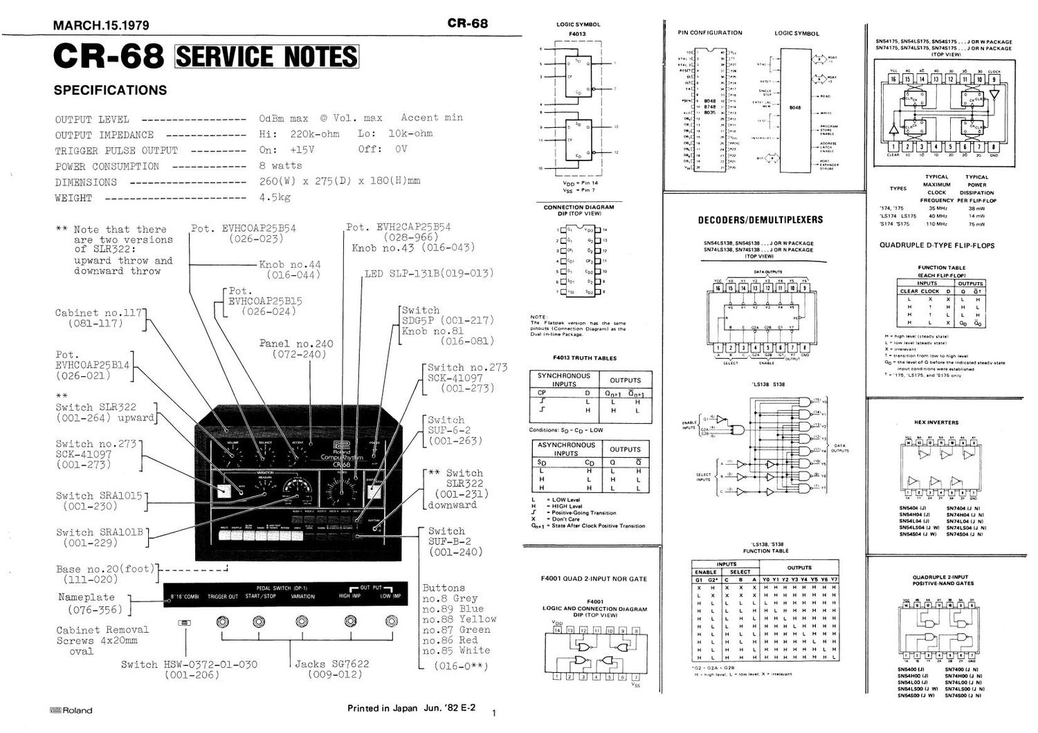
ROLAND CR 68

This is the 10 pages manual for ROLAND CR 68.
Read or download the pdf for free. If you want to contribute, please mail your pdfs to info@audioservicemanuals.com.

Page: 1 / 10
left right
ROLAND CR 68

Extracted text from ROLAND CR 68 (Ocr-read)


Page 2

CIR-68

1'
IT

ED

BALANCE VOICES

CY
H}!
M

EMPO

OL- PANEL SWITH ES

OUTPUT
IMP L

VOLUME
ACC EN T

CIRCUIT DESCRIPTION

COMPUTER BOARD GL-lO

The uPD8048 is an 8-bit parallel computer fabricated
on a single sillicon chip. The 8048 contains a 1k x 8
ROM program memory, a 64 X 8 RAM memory, 27 I/O lines,
an 8-bit timer/counter and clock circuits.

Used on this board is a uPD804BC-015 version in which
program and data dedicated to the CR-6B are stored in
the program memory.

1. SCANNING for IDENTIFYING PANEL SWITCH SETTINGS

The uPD8048 reads panel switch settings by scanning
the lines through Port 2 (P24-P27) of Io1<>,ICB (74LS-
138, Decoder) and Port 1 (PlO-Pl7) of 1010. The out-
put from ICES (Binary-td-octal decoder) goes through
one of properly arranged switches and matrix to port I
For example let's assume that SWING switch is de-
pressed. When A input of 108 is high and B, C and G2B
inputs are low as shown in Fig. l. The output of 1
goes low and other outputs go high.

Since Port 1 (PlO-Pl7) functions now as an input port
and l of ICES is low with SWING switch on, only P10 of
1010 goes low. IClO reads this condition of Port 1
and identifies that SWING switch is depressed. By re- 3
peating such scanning, the computer can identify eve-
ry switch setting in sequence.

This scanning and reading, in STOP mode,are performed
continously in Very short periods by pulses with du-
rations of several microsecons,bur after START switch
is pressed, this scanning is performed once a measure
-- just before the measure is initiated.

2. SENDING OUT RHYTHM PATTERNS

After panel settings are identified as described

above, the data corresponding to the identification
is selected from contains of the ROM and fed into
Port 1 and Port 2.

Tow 74LSl38's [(108 and I09) are used in parallel to
constitute a binary-to-hexadecimal decoder. In this

case, Port 1 of 1010 functions as an output port.

3. VARIATION TURNED ON WITH MANUAL BUTTON

Since the computer reads data once in one measure,if
MANUAL button is pressed during the period between
one reading and another, a circuit is required to
memorize the switching, which consists of 104
(74LSOO) and other components.

IC4a and IC4b constitute an RS flip-flop which is re-
set when START/STOP button is tapped to start the

rhythm unit. When reset in this way, pin 3 of IC4a
goes high, and pin 6 of 10410 goes low and hereafter
this condition is held.

In reading, with MANUAL button off, pin 6 of IC4b
remains low and pin 8 of IC4c is held high independ-
ent of the condition of pin 10 of ICAc. When MANUAL
button is pressed, pin 5 of IC4b immediately goes
low and RS flip-flop is set. Pin 3 of IC4a goes low
and pin 6 of IC4b goes high and this condition is
held.

When a negative going pulse is sent out from 4 of 108
while reading switch positions, the pulse is inverted
by IC2c and this inverted positive pulse is fed to
pin 10 of IC4c. Since pin 9 of IC4c is kept high, a
negative going pulse is sent out from pin 8 of 1040
and fed into Port 1 through D209. Thus, the computer
detects that MANUAL button has been pressed.

Immediately after reading, the computer sends out a
negative going pulse from 0 of ICE to reset RS flip-
flop. To prevent malfunction, this pulse (after in-
vertion by IC2a) and a pulse from ALE of IClO are

NANDed to produce a reset pulse. see Fig. 2

4. CLOCK GENERATOR IC3e, IC3f

This circuit,a clock generator from which pulses are
emitted to synchronize the operations carried out by
the computer, is a CR oscillator consisting of 103e,
IC3f and other components. The oscillator generates
clock signals of about 3MHZ which are fed to XTAL
pin of 1010.

5. MASTER OSCILLATOR C2101, C2102

This oscillator determines the tempo of the rythm and
is a multivibrator consisting of QlOl, Q102 and other
components, whose oscillation period is variable from
101313 - 200ms with TEMPO control V'R2.

6. START CIRCUIT 105b, ICla - ICld, IC2b

This circuit consists of 1C5b (D flip-flop) and other
components. The output "Q" on pin 1 of ICSb is con-
nected to T1 of I010.

Immediately after POWER switch is set to ON a short
positive going pulse with the time constant of R212
and 0208 is generated at pin 11 of ICld and resets
I05b. Q on pin 1 goes low and Q on pin 2 goes high.
Consequently, when POWER switch is set to ON, IClO is
always set in the idling mode.(When T1 of 1010 is low,
the computer stops all functions except scanning).
When START button is pressed, a positive pulse is gen-
erated at pin 4 of IClb which is fed into pin 3 of

ICSb. Q goes high and 5 goes low. Then T1 of 1010
goes high to: start the rhythm unit.

The one shot pulse generator consisting of ICla, IClc,
ICZb and other components detects the leading edge
of an output waveform from Q on pin 1 of ICSb and gen-

erates a pulse with a duration of about 301115 which
resets the master oscillator when the rhythm unit
starts. see Fig. 3

7. FOOT SWITCH CIRCUIT IC3a - IC3d

The foot switch circuit for START/STOP consisting of
ICBa, IC3?) and other components, and that for VARIA-
TION consisting of IC3c,IC3d and other components,are
almost the same circuit. A CR time constant circuit

combined with a schmitt trigger circuit is used to
prevent malfunction caused by foot switch chattering.

MARCH.15.1979
8. DIVIDER IC7a, 105a, ICoa, ICéb

To send out clock pulses with 8 beat and 16 beat to
TRIGGER OUT jack, a circuit is required to divide the
output signals from the master oscillator into 1/3
and 1/6. The circuit consists of four MCl40l3B's
(D flip-flop, IC7a, 105a, 106a, and ICSb) and other
components. IC7a, used as an inverter, shapes output
waveforms from the master oscillator to prevent the
divide-by-3 circuit from malfunctioning. The singals
are fed into the divide-by-3 circuit consisting of
ICBa and Ich to be converted to signals with 16 beat
and sent from Q on pin 1 of 1C6b.

Signals fed from Q on pin 2 of IC6b to CF on pin 11
of 106a are divided again to be converted to signals
with 8 beat and sent out from Q on pin 13 of I06a.
see Fig.4

VOICING BOARD VG-12
l. LATCH ICl -- IC3

This circuit,consisting of three 74LSl75 flip-flops,
take output pulses to be latched from Port 1 and Port
2 through IC2d and ICZe (clock), and take pulses from
the master oscillator to clear the preceding latch,
producing 5V positive going pulse, i.e. rhythm pat-
tern, with the same duration as output pulse of the
master oscillator.
The output pulses from the flip-flops are converted
by Q25-Q35 into negative going pulses with a +15V-OV
swing and fed into inputs of the voicing circuits.
see Fig. 5

2. ACCENT CIRCUIT C221, Q24, V'R14

This circuit is used to add accent to a rhythm ac-
cording to a preset accent pattern by changing the
sound level at the output amplifier. The circuit
consists of the ACCENT (m4), Q21, 024 and other
components. An accent pulse from Q on pin 3 of 101
passes through Q21 and then is differentiated and in-
tergrated to be converted to a proper envelope signal
which is fed into the gate of FET (Q24).

Q24 is off when a signal is not provided at the gate.
In this case, the voltage of the output signal from
Q9 is divided by the ratio of R137 (6Bk-ohm) to the
input impedance of Q10 and is fed into Q10. When a
signal is fed into the gate, Q24 is turned on.

With ACCENT control at 10, most the signal flows into
the accent potentiometer and Q24, but very little
into R137, giving a high level output signal which is
used to add accent.

3. LEAKAGE SOUND KILLER Q20, Q23

These circuits are designed to kill sound from the
voicing circuits generated by transient voltage when
power is turned on or off. When power is on, Q20 will
not function normally until 079 charges enough in re-
spect to the emitter.

The voltage drop at the gate of Q23 is quicker than
it is at the drain or source after trun, so that Q23
is shut off.