ROLAND A 80

This is the 21 pages manual for ROLAND A 80.
Read or download the pdf for free. If you want to contribute, please mail your pdfs to info@audioservicemanuals.com.

Page: 1 / 21
left right
ROLAND A 80

Extracted text from ROLAND A 80 (Ocr-read)


Page 1

MAY 1939

A-80

A-80 SERVICE N0TES
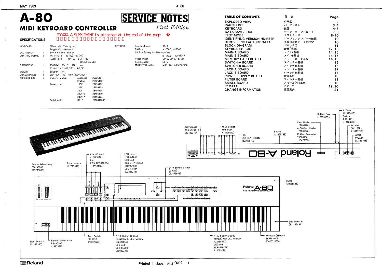
EXPLODED VIEW 9%. 2
' 1 1 PARTS LIST /\°-7 I) 2 |~ 3 I4
MIDI KEYBOARD CONTROLLER FZVSZL Edztzon KEYBOARD ma 4-6
- DATA SAVE/LOAD -?-7 t-j/EI- F 7 .8
EWTA&SLPPLE1\H\1TIS attached at the end of the page. 0 TEST MODE ixbf-F 8-10
SPECIFICATIONS [1 I] I] I] E III I] D I] I] D D [1 I] I] I] E III IDENTIFYING VERSION NUMBER /\-95>+>/\-MEE2 10
RECOVERING FACTORY DATA Iffitflfifi?- 51' 03%? 1O
KEYBOARD 88key, with Velocity and OPTIONS Keyboard stand Ks-7 BLOCK DIAGRAM 7 1:1 1 7-1 1
Polyphonic aftertouch RAM card M-256D, M-256E KEYBOARD LCD DISPLAV 240 x 64 dots display Lithium Battery for Memory Card MAIN-A BOARD x 1 >A§1fi 14 ,15
CONTROL PEDAL Fc 1-Fc 4 0v(00) -5v(7F> CR~2032 12569249 MAIN-B BOARD )1 4 £145 14 ,15
PATCH SHIFT ON 5v ; OFF 0v Pedal switch DP-Z, DP-s, FS-su MEMORY CARD BOARD X-é I) -71-- rag 14 15
(Pedal switch) Volume pedal EV-5 SWITCH-A BOARD x f .7 9'. A $15 16
DIMENSIONS 1360(W)x 354(D)x 118(H)mm MIDI/SYNC cab|es Msc~07/15/25/50/100 SWITCH-B BOARD 14 0/ .7. B £714? 16
WSW 3:111:13, 1* [1345/ 6 X 4'5/8" JACK-A BOARD 3, 5 '7 7 A $15 17
g JACK-B BOARD yr-yaagm 17
$253312 gw°,°"'h;"">l Wjv'zwv 26025481 POWER SUPPLY BOARD mam 18
5 5 W" 5:71"? 26025482 FILTER BOARD 7 4 w -£1fi 18
Power cord 100v 23495112 SMALL BOARD XffMNgfi 18
117v 13499109 '0 DATA I737"? 19 .20
2201/ 23495125 CHANGE INFORMATION aiilfl 21
240v-E 23495110
240v-A 23495124
Pedal switch DP-Z 7710610000
- P. Cover
Rubber Foot (22925413)
(12359105) 2337"
Card Holder (13169503)
(22200188) - Ac Inlet
jicgfgi'gg74- ' $32236. A-50 Card Holder CW 1 (3P)
(13449275) (13429642) mm (22205246) 329"
- P010 (21135188) IC Card Connector _ Switch
EVJ-ELA-EOZBM 75030951) w1<2444
(13279810) 3429233) (13149108)
RD-300 Knob LCD Cover 69 96> H) T DB .V pue|oH CE Eda]
(22465126) (22045164)
Pot. LCD Unit
Escutcheon EWA-NP5X1 0814 TLX-711A-30TA1
233350339 As (22225332) (13339476) (15029433) s-10 Button 5 black
(23275893) LCD dd (5mm)
(22205242) (22475658)

Roland A. a 0

Ma Kevm mum!

Panel
(22215624)

Side Board R
(21125349)

Tact Switch 8-10 Button D black A-SO Button D gray Keyboard(88keys)
. Bender Lever Assy SKHHDC (single)with LED window (single)with LED window SK-BBB-HW
SIde Board I- _ 102 (13169693) (22475656) (22495577) (7620320000)
(21125350) (283505392) LED red LED red
SLR-55VC3F SLR-ssvczF
(15029222) (15029222)
@Roland Printed in Japan AI-2 (DP) 1

Page 5

MAY 1989

SK-6 Rubber Switch Sheet

Difference Between Natural and Sharp Contacts -
- Height -

With rubber switch 12 PW218-224 for SK-6 keyboard,
natural-key and sharp-key contacts are made to different
dimensions. See the figures below and note the height of
contacts.

When replacing contacts, attach the sheet in place, i.e.
match characters with keys. Do not cut the sheet at a
point other than V-cut with a groove.

NOTE

Replacement SK-G keyboard and replacement contact
PCB are equipped with a complate set of rubber sheets.
Sheets are also available as separate replacement.

SK-Sfiir-Xf'fi-tx-Hflm
Elfifltfllfifiwfififl ------ I3 ~~~~~~

s K-eéfififiimamv- r x4 ~v #12 Pw218-224
waseauemm WHELI 0 3'93 Flu/1s? ce < .
fififiéaiifimfifiem.

tfiéiézfifiaélgi: ~7- rtofia%i§0 KEEE L. HIRE?
igéliififilSfiCHJfiiL'CFéha

*i

,

s K-G %Ri:x4-7+Pcs%iu1 X4 +y- r mam
recto

mm. 14 ~7+y-r$i$'0ts%i£ilfi-0¢o

-©+"©-v>-.' 6" +~7~~©©~*
PM ,' JflW'Q flQ m 6. - .m' m '3 P-M-
S.M. rhllilQlellKélgwvikgct «._ S.M.
i¥e¥¢§e¥ \E-Qkfi/Gsa s 4&9; _v\
Designation
h
V v
P.M. SM.

NATURAL KEY

0-40? RUBBE R
CONTACT

SHARP KEY

SK-G KEY REMOVAL LEVER

A lever as shown in Fig. 1 is required in SK-6 key re-
moval.

Consult your local Roland service center for availa-
bility. If not available, make a lever following the in-
structions described below.

3mm

9mm

A-80

SK-6 m9; I/I\'--

SK-GWfifigfifoifi- emflflcii Fig.1l27Ti9Liifit 1/
It-fiJZE'Gh Aime L'CliU-fi y FOW- Ex
chwaraweerem

6mm

__a-T DIMENSIONS IN FULL SCALE sq

7mm

16mm

84mm

Fig. 1

SUBSTITUTIVE LEVER

1. Prepare a length of wire (more than 95mm or 3.8
in.). A paper clip is a most typical one.

2. (If a coiled wire as example of a paper clip.)
Uncoil and straigten the wire.

3. Reshape the wire to Fig. 2, with the dimensions
exactly matching the values given in the figure.

4. Prepare a separate key (may be a replacement to
be used, natural or black.).

5. Grasp key and key holder at G) in Fig. 3 with
thumb and forefinger to allow the holder goes to
the bottom. Retain tension on holder at this
point. And insert the key removal lever into key
to hook the latch lock. ® in Fig. 3.

6. Release key holder. When the holder remains
locked, (Z, the lever you made now passes the
acceptance test. and ready to work on the
keyboard.

0 l
l

@

lz/t-U)fE§H¥I§

WflLVN~fiflw%fiuT%¥fiTWfiLTTéWo

1.ae a

z.:®%$%mgzmfiiiufififfi0mweo

3.fi@m®$-(EfibL

4. Fig.3m®m§l§fiéo7§>$$-$MMfiéiflm
cofificfie®%%fie-*»ymvxumofl
libfiil:#-J:%M*Bi§la6®o e-nwwpe
$22. Fig. solstice-awvmmwam;
fifléeovao

film C533

16mm {}

7mm

:Dfiafige

DIMENSIONS IN FULL SCALE id