Rogers ravensbourne service manual

This is the 10 pages manual for rogers ravensbourne service manual.
Read or download the pdf for free. If you want to contribute, please mail your pdfs to info@audioservicemanuals.com.

Page: 1 / 10
left right
rogers ravensbourne service manual

Extracted text from rogers ravensbourne service manual (Ocr-read)


Page 1

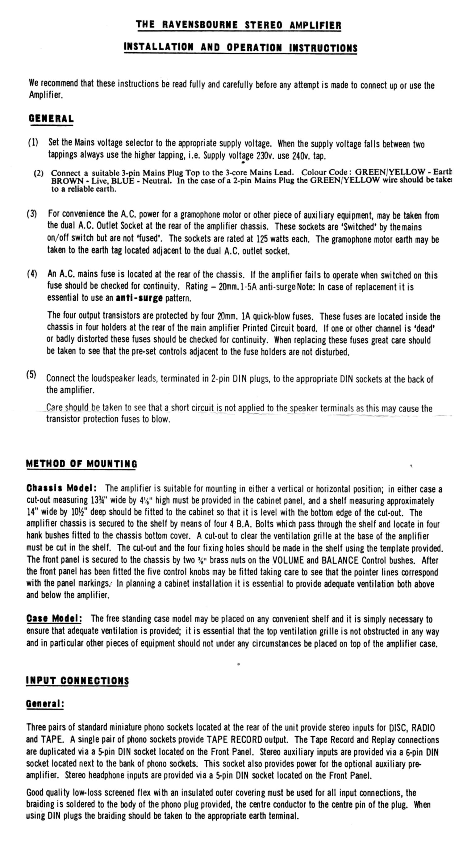
THE BAVENSBOUBIE STEREO AMPLIFIER

rusuLLmou AIID openA'rrgLers'rnycflous

We recommend that these instructions be read fully and carefully before any attempt is made to connect up or use the
Amplifier.

GENERAL

( 1) Set the Mains voltage selector to the appropriate supply voltage. When the supply voltage falls between two
tappings always use the higher tapping, i.e. Supply voltage 230v. use 240v. tap.

2 Connect a suitable 3- in Mains Plug Top to the 3-core Mains Lead. Colour Code: GREEN/YELLOW - Earth
( ) BROWN - Live, BLUE - Neutral. In the case of' a 2-pin Mains Plug the GREENIYELLOW wrre should be taker

to a reliable earth.

(3) For convenience the A.C. power for a gramophone motor or other piece of auxiliary equipment, may be taken from
the dual A.C. Outlet Socket at the rear of the amplifier chassis. These sockets are Switched' by the mains
on/off switch but are not fused'. The sockets are rated at 125 watts each. The gramophone motor earth may be
taken to the earth tag located adjacent to the dual A.C. outlet socket.

(4) An A.C. mains fuse is located at the rear of the chassis. If the amplifier fails to operate when switched on this
fuse should be checked for continuity. Rating - 20rnm.1-5A anti-surge Note: In case of replacement it is
essential to use an arm-surge pattern.

The four output transistors are protected by four 20mm. 1A quick-blow fuses. These fuses are located inside the
chassis in four holders at the rear of the main amplifier Printed Circuit board. If one or other channel is dead'
or badly distorted these fuses should be checked for continuity. When replacing these fuses great care should
be taken to see that the preset controls adjacent to the fuse holders are not disturbed.

(5) Connect the loudspeaker leads, terminated in 2-pin DIN plugs, to the appropriate DIN sockets at the back of
the amplifier.

Care should be taken to see that a short circuit is not applied to the speaker terminals as this may cause the
transistor protection fuses to blow.

memo or mourmrre

Ghaesls Model: The amplifier is suitable for mounting in either a vertical or horizontal position; in either case a
cut-out measuring 13%" wide by 4V." high must be provided in the cabinet panel, and a shelf measuring approximately
14" wide by 10%" deep should be fitted to the cabinet so that it is level with the bottom edge of the cut-out. The
amplifier chassis is secured to the shelf by means of four 4 B.A. Bolts which pass through the shelf and locate in four
hank bushes fitted to the chassis bottom cover. A cut-out to clear the ventilation grille at the base of the amplifier
must be cut in the shelf. The cut-out and the four fixing holes should be made in the shelf using the template provided.
The front panel is secured to the chassis by two 9/." brass nuts on the VOLUME and BALANCE Control bushes. After
the front panel has been fitted the five control knobs may be fitted taking care to see that the pointer lines correspond
with the panel markings: In planning a cabinet installation it is essential to provide adequate ventilation both above
and below the amplifier.

Base Model: The free standing case model may be placed on any convenient shelf and it is simply necessary to
ensure that adequate ventilation is provided; it is essential that the top ventilation grille is not obstructed in any way
and in particular other pieces of equipment should not under any circumstances be placed on top of the amplifier case.

IIIPIIT OOIIIIEBTIOIIS
General:

Three pairs of standard miniature phono sockets located at the rear of the unit provide stereo inputs for DISC, RADIO
and TAPE. A single pair of phono sockets provide TAPE RECORD output. The Tape Record and Replay connections
are duplicated via a 5-pin DIN socket located on the Front Panel. Stereo auxiliary inputs are provided via a 6-pin DIN
socket located next to the bank of phono sockets. This socket also provides power for the optional auxiliary pre-
amplifier. Stereo headphone inputs are provided via a 5-pin DIN socket located on the Front Panel.

Good quality low-loss screened flex with an insulated outer covering must be used for all input connections, the
braiding is soldered to the body of the phono plug provided, the centre conductor to the centre pin of the plug. When
using DIN plugs the braiding should be taken to the appropriate earth terminal.

Page 2

DISC: BLUE

WEE?!

"3AM; REPLAI: RED .,

MAINS
. voume m t T
V 5,). .' .
4

MAINS
LZAD
LOUDSIEAKEI OWNTS
A.C.WTLET SOCKETS LEFT IIGN'I
O
O O

O O

DISC (Socket Colour Code Black)

A two-button disc sensitivity switch, located next to the auxiliary socket, provides four alternative Disc
Sensitivities as follows :-

1. IN 2. OUT 75m/V. 1. OUT 2. OUT 50m/V. 1. IN 2. IN 3m/V. 1. OUT 2. IN 2m/V.

The above sensitivities for 25 watts output. All inputs have an impedence of 50K. RIAA Compensated.

The sensitivity best suited to the pick-up cartridge being used can be determined by reference to the manu-
facturer's pick-up data.

The sensitivity switch should only be operated with the volume control at minimum setting.
When connecting the pickup lead. on no account should the braiding be earthed to the motor or amplifier chassis

earth. The braiding will automatically be earthed at the correct point when the phono plug is inserted in the
disc socket.

RADIO (Socket Colour Code Red)

Dual radio inputs are provided suitable for the connection of the majority of AM, FM and FM Stereo Radio
Receivers.

Sensitivity 200m/V (for 25 watts) Impedance 100K.

TAPE REPLAY (Socket Colour Code Green)

Dual tape replay inputs are provided suitable for the connection of the majority of complete Tme Recorders. These
connections are duplicated at the 5-pin DIN Socket located on the front panel. All controls are Operative on replay.

Sensitivity 2mm/V (for 25 watts) Impedance 100K. The source impedance is not critical.

TAPE HEOOBD (Socket Colour Code Blue)

Dual tape record outputs are provided suitable for connection to the majority of complete Tape Recorders. These
connections are duplicated at the 5-pin DIN Socket located on the Front Panel. Whatever programme source is
selected will appear at the Record Sockets and will be unaffected by the settings of the Volume, Tone and Filter
Controls. Only the mono L and mono R buttons will affect the tape record outputs.

We must emphasise that the record signal is not suitable for feeding direct to tape record heads, a tape deck alone
is therefore not sufficient and a complete tape recorder incorporating a record amplifier and bias oscillator is
essential. Record outputs 200m/ V for rated input sensitivities. Minimum external source impedance lmK.ohms.

AUXILIARY

Dual auxiliary inputs are provided via a 6-pin DIN socket located next to the bank of phono sockets. Power for an
optional transistorised pro-amplifier may also be drawn from this socket. Preamplifiers are available providing
inputs for Tape Head Replay, Microphone and Second Pick-up. Using the Tape Head pro-amplifier it is possible to
copy tapes from one recorder to another.

Sensitivity (without pre-amplifier) 200le (for 25 watts) liDKchms.