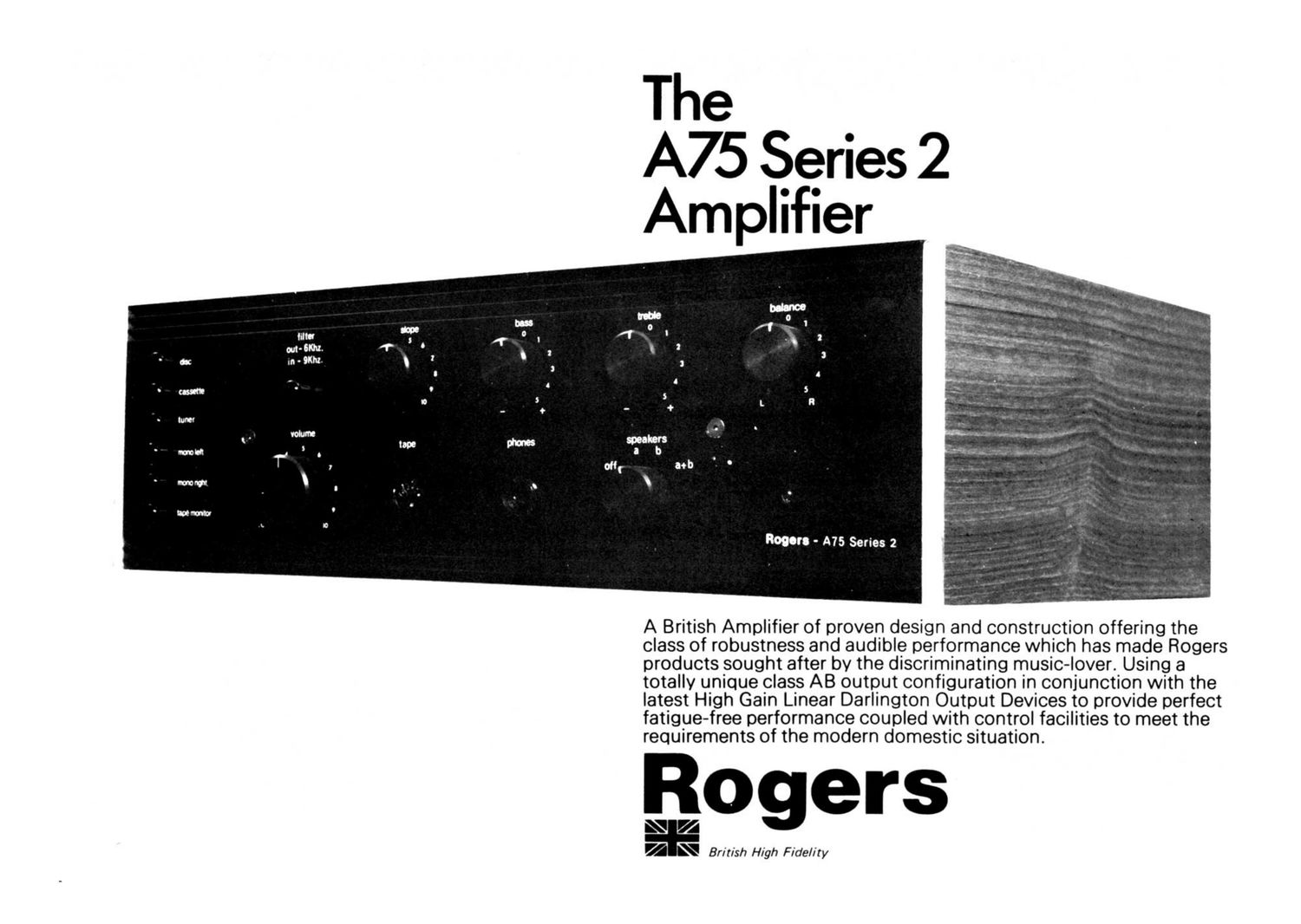
Rogers panthera a75 2 brochure

This is the 2 pages manual for rogers panthera a75 2 brochure.
Read or download the pdf for free. If you want to contribute, please mail your pdfs to info@audioservicemanuals.com.

Page: 1 / 2
left right
rogers panthera a75 2 brochure

Extracted text from rogers panthera a75 2 brochure (Ocr-read)


Page 1

The

A75 Series 2
Amplifier

Rogers - A75 Series 2

A British Amplifier of proven design and construction offering the
class of robustness and audible performance which has made Rogers
products sought after by the discriminating music-lover. Using a
totally unique class AB output configuration in conjunction with the
latest High Gain Linear Darlington Output Devices to provide perfect
fatigue-free performance coupled with control facilities to meet the
requirements of the modern domestic situation.

Rogers

L\V <4
7 Brit/sh High Fidelity

Page 2

A75 Series 2
Amplifier

A truly British product of legendary Rogers reliability
featuring: -

Output power of 45 + 45 w continuous sine wave
power 30 Hz - 40 KHz both channels driven into 8
ohm loads.

Distortion less than 0.08% at I KHz at any power
below clipping both channels driven into 8 ohm
loads

FaCilities for cassette and open reel recorders wrth
dubbing and transfer faCilities.

Selection of either or both of two pairs of stereo
loudspeakers coupled with headphone facilities.
DC. Coupled loudspeaker outputs for superior bass
reproduction.

Comprehensrve variable slope filtering of selectable
frequency - acknowledged as the only useful
method of filter control.

Three swuched A.C. mains outlets usmg approved
shuttered Eurosocket connectors.

The ideal amplifier for accurate reproduction in
coniunction With the Rogers BBC desrgn derived
loudspeakers.

The main characteristic which has distinguished
Rogers amplifiers from impresswely specified
competitors' products is the superb sound
reproduction. The Rogers A75 Series II possesses
audible performance which distingmshes it from
virtually all other amplifiers and has led to the Rogers
reputation amongst true ntuSic-lovers,

Technical Speci

INPUT FACILITIES

DISC
(Magnetic or Ceramic)

TUNER

CASSETTE

TAPE

OUTPUT FACILITIES
CASSETTE RECORD

TAPE RECORD

POWER

PHONES

SPEAKERS

Selected bv front push buttons

SenSItiVities are for 45 watts into

8 ohms

Input impedance 47K ohms

Input connection 5 Pin DIN socket on
rear panel

Response Equalised to R I A A 1 Idb

Sensmvitv 2 7 mV, dmv, 63 mV and
90 mV at l KHz lSelected bv rear
panel push buttons)

Overload better than 80 mv at mm
on the 2 7 mV senSltiwtv

Note 1 Ceramic pickups can be used
feeding into low impedance
R l A A EduaIised inputs and some
manufacturers speCifv additional
correction networks for such
applications

Note 2 See Mode Selection for playing
Mono records With a stereo pickup

Sensuivitv tBOmV

Input Impedance 100 K ohms in
Stereo mode

Overload Infinite for all practical
applications

Replay Sensrtrvrtv 180 mV

Input Impedance 100 K ohms in stereo
mode

Overload Infinite for all practical
applications

Replav Sensrtrvrtv I80 mV

Input Impedance 100 K ohms in stereo
mode

Overload Infinite for all practical
applications

Input Connection 5 Pin DIN standard
socket on rear panel and duplicated
on front panel

TREBLE
VOLUME

FILTERS

MODE SELECTION
LEFT AND RIGHT

STEREO OR MONO

Signal levels for rated inputs

Record level 180 mV in series With
330 K ohms Suitable for most DIN
Standard inputs

Output Connection 5 Pin DIN socket
on rear panel

Record level 180 mV

Load impedance 50 K Ohms or greater

Output connectiOns 5 Pin DIN
standard socket on rear panel and
duplicated on front panel

3 SWitched A C Power Outlets lTotal
vlakirrturri Permitted I out! 2-10 wattsl

Standard "i " stereo iack socket on
front panel

Maximum level 20 Volts in series With
150 ohms (Suitable for most
headphones 018 300 ohms
impedancel

PERFORMANCE
OUTPUT
CONFIGURATION
Connection Single pole sockets to
.itzi..ornrriotfale heavv dutv 4mm
'i'iw toritact remstanrfi plugs
Selection by front panel control of two
irirt vidtml sets OI SIGIGO
loudspeakers A or B With addITIOTtal
lgii'ilrtv of selecting A and 8
si'iiiiltarieouslv and of svvitching off
iIII loudspeakers while retainiriu
fiinidtihotw ()LITLILJT

OLI T PU T ROWE R

TONE AND VOLUME CONTROLS

BASS

Rt mi! v r. t'ihtrtil tilliiwirtii up to 16 at)
[ii PST 7' 1i.'. 9' 34 H:

EOWE R SAND "WIDTH

Iicolion

Rotary control allowmg up to 16d!)
boost or cut at 10 KHz

Rotary legarithmic control to allow
smooth increase in output level

HIGH PASS Fixed at 20 Hz With a
slope of approximately 30 db per
octave

IOW PASS Two priSitit'ir variabre
slope filter vvith a 6 KHz or 9 KHz
turnover frequencv selected by a
front panel push button With the
slope being continuatislv variable
between zero and 20 db per octave
by a rotary front panel control

All dual controls are close tolerance
potentiometers to allow accurate
tracking between left and right hand
iThi'i'trwlt',

Front panel push buttons give the
Iollowmg faCilities on Radio.
Cassette and tape inputs

Left and right inputs to left and right
outputs for stereo operatiOn

Left input applied to left and right
outputs

Right input applied to left and right
outputs

Selection of a Single track on a 'n or I.
track open reel recorder for playing
back on both amplifier channels can
be achieved usmg Mono left 0r
Mono right input buttons

Front panel push button allows the
left and right disc inputs to be
connected in parallel and applied to
both amplifier channels (For use
vvith stereo pickups playing mono
recordsl

CASSETTE - OPEN REEL RECORDERS

Facilities include

Recording from disc, radio or cassette
on to an open reel recorder

Recording from disc, radio or open reel
recorder on to a cassette recorder

Replay from a cassette recmder

Replay from a 3 head open reel
recorder wrth tape monitoring
button allowmg A/B comparison
between the original Signal being
recorded and the recorded Signal

Class AB emploving D C Loudspeaker
c0up|ing usmg Darlington linear
high gain Output devices and a
unique drive Circuit configuration

Continuous Sine Wave

45 i 45 watts into 8 ohms
30 HI I!) KHZ 80th Channels
driver.

36 . 36 watts into 4 ohms
30 H1 30 KHz Both channels
driven

2E . 2'8 watts into l5 ohms
30 Hz 30 KHz Both channels
driven

"iii!" ' -.i:;v'iii"*' fiftli'fti"i"\ :Iiiti
r . r a .
Sig'f A." "i.

TOTAL HARMONIC
DISTORTION
lboth channels drivenl

less than 0 08% at I KHz at raw power

up to 40 watts into 8 ohms load

Less than 0 3% 40 H1 20 KHz at any
power up to 40 watts into 8 ohm

load
DAMPING FACTOR 30at 50 Ht ref IO watts into 8rihrris
BALANCE CONTROL 9db range
SIGNAL TO NOISE Disc betterthar 70 dblCCIR
weightingl

All other inputs better tliar 80 db

ICCIR weighlirigl

FREQUENCY Disc R l A A Eoualisation : Idb
RESPONSE All other inputs 1 1 db 25 HI
ZOKHI
; 2dt'i90 HI DOKHI

STEREO SEPARATION Better than 52 db at l KHz vvith dlSC
input at makimum SQFISITIVITV and
Output level of 45 watts into 8 ohm
load
POWER SUPPLY Balanced posnive and negative Supplv
rails emploving capaCitor smoothing
and fast acting fuses for unobttuSive
operation With complete amplifier
and loudspeaker protection

IIO/I20/220/240v 50-60 Hz
A C Mains

Maximum output 200 watts

RANGE
lSet Internally)

CONSUMPTION

TRANSISTOR COMPLEMENT

14 Silicon small Signal TranSistors
4 Silicon power driver Tran5istors
4 Silicon Darlington output deVices

DIMENSIONS 36 2 cm x 286cm it It 7 cm
(14V."x11/i"x4'6")
WEIGHT 7 Kg (15% lbs)

The manufacturers reserve the right to a/ter
specifications Without prior notice.

Distribution restricted to appointed Retail Dealers
and Professional Users.

*1
7 V British High Fidelity

All Rogers high fidelity products are manufactured
and distributed by:

SWISSTONE ELECTRONICS
LIMITED

Main works
4/14 Barmeston Road, London SE6 3BN.
Telephone: 01-697851 1.

Cables: Swisselec London SE6