Rogers cadet mk2 owners manual

This is the 7 pages manual for rogers cadet mk2 owners manual.
Read or download the pdf for free. If you want to contribute, please mail your pdfs to info@audioservicemanuals.com.

Page: 1 / 7
left right
rogers cadet mk2 owners manual

Extracted text from rogers cadet mk2 owners manual (Ocr-read)


Page 1

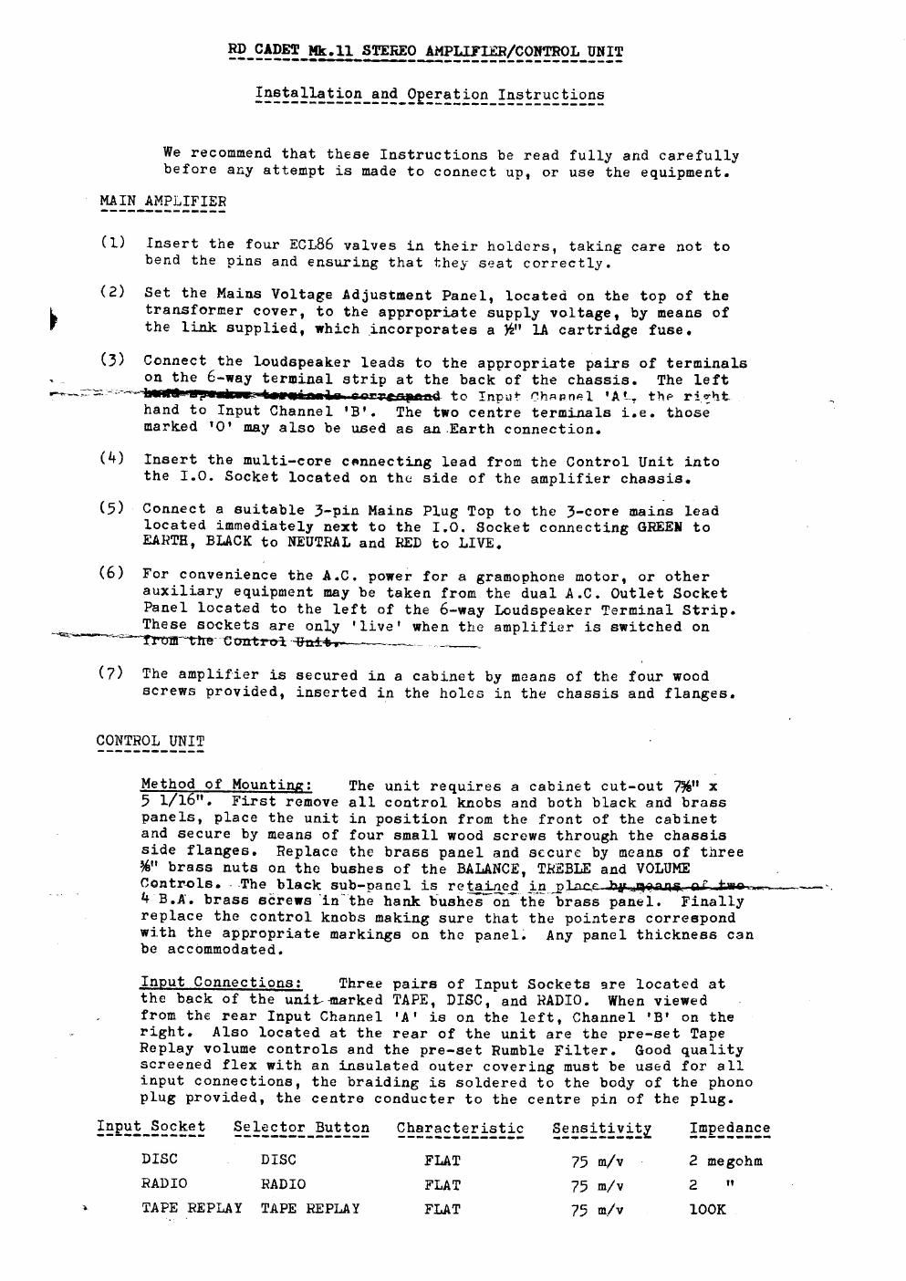
BPEQEELfliTEBEEAEEE-HEBZSQMLEET

£25SEEEEEEEE_EEQ_QBEEEEESE_§E§EEEEEiEE§

We recommend that these Instructions be read fully and carefully
before any attempt is made to connect up, or use the equipment.

MAIN AMPLIFIER

(1) Insert the four ECL86 valves in their holders, taking care not to
bend the pins and ensuring that they seat correctly.

(2) Set the Mains Voltage Adjustment Panel, located on the top of the
F transformer cover, to the appropriate supply voltage, by means of
the link supplied, which incorporates a k" 1A cartridge fuse.

(3) Connect the loudspeaker leads to the appropriate pairs of terminals
. on the 6-way terminal strip at the back of the chassis. The left
rv~£3;: . ' to Input flheanel 'Alc the right
hand to Input Channel 3. The two centre terminals i.e. those
marked '0 may also be used as an.Earth connection.

we

(4) Insert the multi-core connecting lead from the Control Unit into
the 1.0. Socket located on the side of the amplifier chassis.

(5) Connect a suitable 3-pin Mains Plug Top to the j-core mains lead
located immediately next to the 1.0. Socket connecting GREEN to
EARTH, BLACK to NEUTRAL and RED to LIVE.

(6) For convenience the A.C. power for a gramophone motor, or other
auxiliary equipment may be taken from the dual A.C. Outlet Socket
Panel located to the left of the 6-way Loudspeaker Terminal Strip.
fla These sockets are only 'live' when the amplifier is switched on
"t"ITUETnEControi~{hflflh-~a--~e~" .ii_.r

(7) The amplifier is secured in a cabinet by means of the four wood
screws provided, inserted in the holes in the chassis and flanges.

CONTROL UNIT

Method of Mounting: The unit requires a cabinet cut-out 7%" x

5 1/1 ". First remove all control knobs and both black and brass
panels, place the unit in position from the front of the cabinet
and secure by means of four small wood screws through the chassis
side flanges. Replace the brass panel and secure by means of three
%" brass nuts on the bushes of the BALANCE, TREBLE and VOLUME
Controls. The black sub-panel is retained ip,plac q,

4 B.A. brass sérews'inmthe hank Bushes-on the brass panel. Finally
replace the control knobs making sure that the pointers correspond
with the appropriate markings on the panel; Any panel thickness can
be accommodated.

Input Connections: Three pairs of Input Sockets are located at
the back of the unitrmarked TAPE, DISC. and RADIO. When viewed

from the rear Input Channel 'A' is on the left, Channel 3' on the
right. Also located at the rear of the unit are the pre-set Tape
Replay volume controls and the pro-set Rumble Filter. Good quality
screened flex with an insulated outer covering must be used for all
input connections, the braiding is soldered to the body of the phone
plug provided, the centre conducter to the centre pin of the plug.

IEEEE_§SE§SE §El§2§2£_§2§§22 QEEEESESEEEEES 222395952
DISC DISC FLAT 2 megohm
RADIO RADIO FLAT 2 "

100K

I TAPE REPLAY TAPE REPLAY FLAT

Page 2

PM) §
* Duplicated via Panel Socket.

TAPE RECORD (via Panel Socketxonly) 250 m/v.

-«- The Disc Input is designed exclusively for use with crystal or
ceramic cartridges. In the majority of cases direct connection, without
additional matching, will give satisfactory results. When in doubt the
individual pick-up manufacturers advice should be sought. When connecting
the pick-up leads on no account should the braiding be earthed to the
motor or main amplifier.

------ Dual radio inputs are provided suitable for the connection of the
majority of AM or FM Receivers.

TAPE , .
---~ A five-way Continental Pattern Panel Socket is provided which

combines the function of TAPE RECORD and TAPE REPLAY and is intended for
the connection of a complete Tape Recorder. The TAPE REPLAY connections
are duplicated at the rear of the unit.

. , ConnCCtiggfiitQW follows:-
. (1) Tape Record Channel A I , WW
'_ ll 1

ES; " " B W
2 " Replay " A CWHn-g'wk-b
()4) H u " B - WM
- (3) LARTH "v i.

A suitable 5-way Flex Plug is provided with each unit.

Whatever programme source is selected will appear at the Tape Record
Sockets and will be unaffected by VOLUME or TONE CONTROL settings.
Recording level will be adjusted by means of the level control on the
Tape Recorder. ' ,

r' n . V l
f§E§E_E§§§}§E With n0_innnifl_snnnectedrand the main volume control at

----*-maxtfium-THE*3ffect of reversing the mains lead should be tested. The

correct connection will be that producing the minimum hum level.

éygigzggaégg With no inputs connected the unit will be found to have a

very low noise level, if there is any substantial increase in hum level
when a pick~up or other auxiliary piece of equipment is connected, then
this indicates incorrect assembly and/or wiring of the auxiliary
equipment concerned. When trouble from hum is experienced the following
points should be checked:-

1. The mains transformer(s) on the amplifier(s) should be located at
least 18 inches away from magnetic pick-ups and tape heads, otherwise
induced hum may result.

2. Check the screening of the pick-up lead; on no account should the
braiding be earthed to the amplifier or the motor, or allowed to touch
the motor plate, metal pick-up arms etc. It will automatically be
earthed at the input socket when the lead is plugged in.

3. The gramophone motor should be earthed to the main amplifier by means
of the socket or tag provided.

CONTROL FACILITIES

EEEHT-§EEEQE9§ Three-position push-button unit providing selection

of DISC, RADIO and TAPE Replay.

Y9§H¥§ Dual ganged Control affecting overall volume from all
inputs. Has no effect on the Tape Record Output.

_____________ ' Two-position toggle switch controls mains supply to
amplifier. In the ON position the amber dial light
will be illuminated.