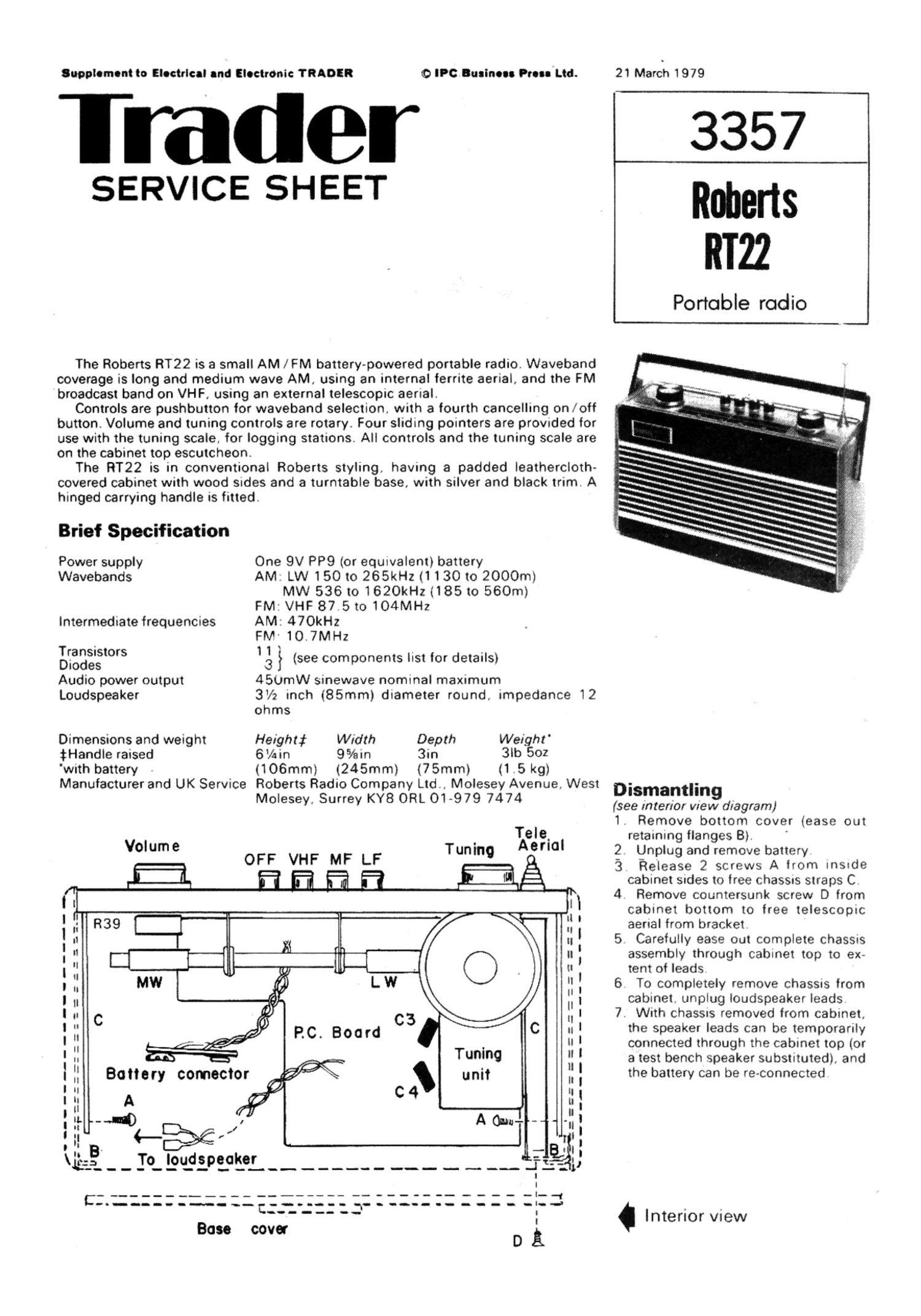
Roberts rt 22 service manual

This is the 3 pages manual for roberts rt 22 service manual.
Read or download the pdf for free. If you want to contribute, please mail your pdfs to info@audioservicemanuals.com.

Page: 1 / 3
left right
roberts rt 22 service manual

Extracted text from roberts rt 22 service manual (Ocr-read)


Page 1

Supplsmsnt to Elsctrlcsl and Elsctmnic TRADER 0 IPC Business Puss Ltd. 21 March 1979

Trader 3357

SERVICE SHEET Roberts
RT22

Portoble rodio

The Roberts RT22 is a small AM / FM battery-powered portable radio. Waveband
coverage is long and medium wave AM, using an internal ferrite aerial, and the FM
broadcast band on VHF, using an external telescopic aerial.

Controls are pushbutton for waveband selection, with a fourth cancelling on loft
button. Volume and tuning controls are rotary. Four sliding pointers are provided for
use with the tuning scale, for logging stations. All controls and the tuning scale are
on the cabinet top escutcheon.

The RT22 is in conventional Roberts styling, having a padded leathercloth-
covered cabinet with wood sides and a turntable base, with silver and black trim. A
hinged carrying handle is fitted.

Brief Specification

Power supply One 9V PP9 (or equivalent) battery
Wavebands AM: LW 150 to 265kHz (1 130 to 2000m)
MW 536 to 1620kHz (185 to 560m)
FM: VHF 87.5 to 104MHz

Intermediate frequencies AM: 470kl-lz
FM- 10.7MH2
Baggzigtors 1:13 } (see components list for details)
Audio power output 4SUmW sinewave nominal maximum
Loudspeaker 3V2 inch (85mm) diameter round, impedance 12
ohms
Dimensions and weight Height: Width Depth Weighr'
tHandle raised 6/4in 9%in 3in 3|b 502
'wrth battery (106mm) (245mm) (75mm) (1.5 kg)
Manufacturer and UK Service Roberts Radio Company Ltd., Molesey Avenue, West Dismantlin
Molesey, Surrey KY8 ORL 01 -979 7474 {see interior vievgd/agram)
1. Remove bottom cover (ease out
Tele. retaining flanges B).
Volume Tuning ABIIOI 2 Unplug and remove battery
OFF VHF MF LF '3 fielease 2 screws A from inSide
E E a a a cabinet Sides to tree ChaSSlS straps C
l I l 4 Remove cauntersunk screw D from
I f 1 cabinet bottom to free telescopic
' " R39 L ' aerial from bracket
! ll 715 u I 5 Carefully ease Out complete chaSSis
' I1 u assembly through cabinet top to ex-
| i: - O y I U l tent of leads.
, H MW L W :i l 6 To completely remove chassrs lrom
: H II I 7 ca/Sintethunplug l0udspdezfaker leads
,. l . it c assrs remove rom cabinet,
I " C PC Board C3 C 1: l the speaker leads can be temporarily
l :1 , ' ' _ II I connected thr0ugh the cabinet top (or
: i. Tum) :: ' a test bench speaker substituted). and
| 1: Bang comector \ unit It : the battery can be re-connected
I ll C 4 It I
| II A u
' ii. ~31) A ON I]:
t .. "' , n il
l .l L F56 , I 'r , I
r " . _. . '
V123 - ._ IO. 199292991. __.___ _ ___ __ __ ___. 3%))

- -_-___ -- ----- - --- -l-fi

C""""""" C..".'_:IZJ' "" "" " " " I'd

. . Interior view
Base cover 3
D

Page 2

Electrical and Electronic TRADER 21 March 1979

oaoc2aoao oao
R32123l® C3l Obolobo obo
C1) EDD OC28 oCo ocoRzaoCo
i234 ses7n24sess d
® R33 I 0 0° o
l] 2 3
20 R3 3 e 00
-c7R453 0T7° ® 5453
ce- 0 C42 ®
® RSI: S) R460 -

0| c27- 816% C29 . c4i
° 35 I E 5
- °3 Mi [1° 2 - * D

Elite 3 3 O


@3237 it, 0%..

O OR?0

Equrpment requrred

AM Signal generator, covering 150 to
1500kHz. modulated 400Hz 30%

FM signal generatOr

Sweep marker generator. sweeping
IOMHz : lMHz.

Oscilloscope. sensitivity lOOmV per
dtvrsion.

Suitable Output meter (VTVM),

lnput matching components as detailed
in text

Preliminaries

Allow test equipment to warm up belore

beginning alignment Progressively

reduce signal input level as crrcurts come
into alignment to avord agc action on

AM, "Limiting" on FM

Procedure

(See printed Circuit and interior view

diagrams for locations of coils. trimmers

and test pomts )

1 Connect meter. set to lOmA range
In series with link 1 on foul side of p c
board AdeSl preset R47 to
minimum Then after 1 minute at
20 C adiust 847 to give reading of
lmA,

2. Check that there is a full 9V d.c
across capacnor C45. and that, With
the tuning gang fully meshed. the
tuning scale pornter coancrdes With the
scale right hand end datum mark

Alignment

AM (select "MF)

LF. Stages

Connect AM Signal generator output
across MW aerial coil primary L3 (on
ferrite aerial). Connect oscrlloscope
input between swrtch 83 contact a
and chassis Tune generator to
470kHz .adiustAM, lFTsT3,T8 and
T6, in that order. for maXimum
amplitude of displayed response, with
symmetrical response about 470kHz
During adjustment keep sugnal input
level so as to maintain a display
amplitude of about 5 dwisions
(SOOmV).

R.F. Stages

lniect rt Signals from AM Signal
generatOr Via inductive loop to ferrite
aerial Connect output meter across
loudspeaker speech cod

MW (select "MF";

1 Tune receiver to h l calibration mark
on tuning scale. and signal generatOr
to 1500kHz. Adiust MW oscrllator
trimmer C30 and r l. trimmer (:23 for
maximum

2 Retune receiver to It. calibration
mark on scale, and signal generator to
560kHz Adiust MW oscdlator corl T7
and aerial c0i| L3 (on ferrite rod) for
maximum.

LW (select "LF")

3. Tune receiver to h .f. calibration mark
on scale and srgnal generator to
260kHz Adjust LW oscillator trimmer
C35 for maximum.

4. Retune receiver to It. calibration
mark, and Signal generator to
156kHz. Adjust LW aerial coil L4 for
maximum.

FM (select "VHF' ')

Note' Only the IF Stages can be
aligned. The FM rt. tuner is a sealed unit
and no attempt should be made to dis
turb the settings.

1. Connect FM generator via sweep
marker, set to sweep 10.7MH2. de~
vrated 1MHz, to test pomt TPl
(remove screened lead to VHF tuner)
Connect osc-lloscope input via diode
probe to test point TP2 (Tr4 collector).
Adjust FM final IF T4 for maximum
amplitude and symmetry of response
on display.

2 Transfer oscilloscope input to bet-
ween iunction 825/826 and chassis.
Adiust FM discriminator T5 until the
Straight part of the "8" curve centre
passes through zero at 10 7MHz.
level -3dB

.4
E
E
(0
I11
I
s
0
m
(D
I
"1
I11
_I
w
w
01
\l
E
a
E"
B
E.
g