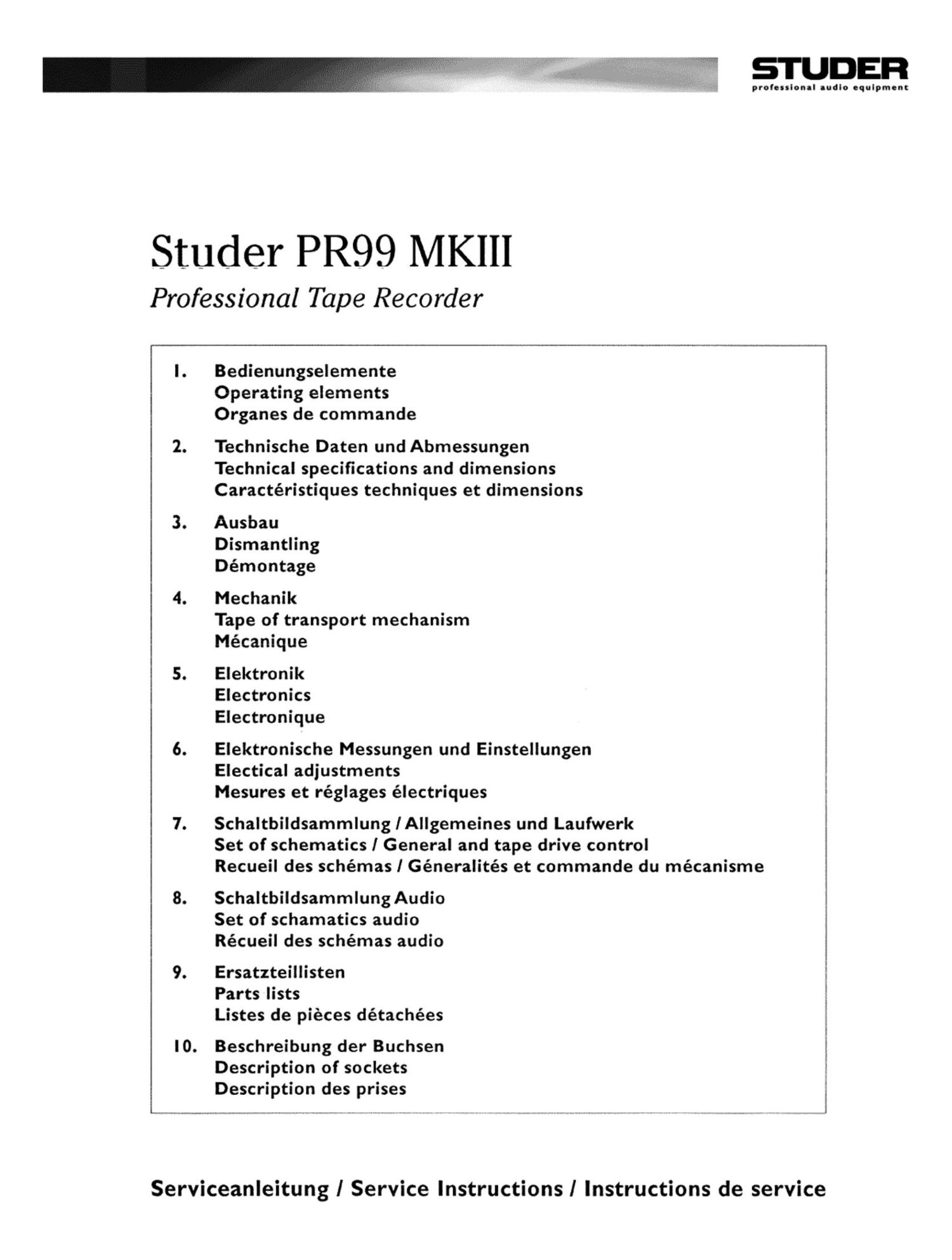
Revox PR 99 MK III Service Manual

This is the 63 pages manual for Revox PR 99 MK III Service Manual.
Read or download the pdf for free. If you want to contribute, please mail your pdfs to info@audioservicemanuals.com.

Page: 1 / 63
left right
Revox PR 99 MK III Service Manual

Extracted text from Revox PR 99 MK III Service Manual (Ocr-read)


Page 1

prolouionll audio oqulpmont

Studer PR99 MKIII

Professional Tape Recorder

I. Bedienungselemente
Operating elements
Organes de commande

2. Technische Daten und Abmessungen
Technical specifications and dimensions
Caractéristiques techniques et dimensions

3. Ausbau
Dismantling
Démontage

4. Mechanik
Tape of transport mechanism
Mécanique

5. Elektronik '
Electronics
Electronique

6. Elektronische Messungen und Einstellungen
Electical adjustments
Mesures et réglages électriques !

7. Schaltbildsammlung lAllgemeines und Laufwerk
Set of schematics I General and tape drive control
Recueil des schémas I Géneralités et commande du mécanisme

8. SchaltbildsammlungAudio
Set of schamatics audio
Récueil des schémas audio

9. Ersatzteillisten
Parts lists
Listes de pieces détachées

l0. Beschreibung der Buchsen !
Description of sockets
Description des prises

Serviceanleitung I Service Instructions] Instructions de service

Page 2

WARTUNG / MAINTENANCE

STUDEFI

SM D-Bauelemente

SMD Components

Der Austausch von SMD-Bauelementen ist ausschliess-
lich geiibten Fachleuten vorbehalten. Fiir verwfistete Pla-
tinen konnen keine Ersatzanspriiche geltend gemacht
werden. Beispiele fiir korrekte und falsche SMD-
Létverbindungcn in dcr Abbildung weitcr unten.

Bei Studer werden keine handelsfiblichen SMD-Teile
bewirtschafiet. Fur Reparaturen sind die notwendigen
Bauteile lokal zu beschafien. Die Spezifikationen von
Spczialbauteilcn finden Sie in der Serviceanleitung.

SMDs should only be replaced by skilled specialists. No
warranty claims will be accepted for circuit boards that
have been ruined. Proper and improper SMD soldering
joints are depicted below.

Studer does not keep any commercially available SMDs
in stock. For repair the corresponding devices should be
purchased locally. The specifications of special components
can be found in the service manual.

SMD-Battleill WolbeNSoldering iron
SMD component
Leiterbahn/
Copper track Winn/Solder
PlaiinelPCB
Kleber/Glue """1**"¢" """
DemontagelDismounling
Vakuum-Kolbenl
Desoooen ' 'ng iron {fix 9 l 0
Lolkolben/ .
Soldering iron Sauglitze/ Saugltze/
Desolder Desolder
wick wick
Heizen und enliemen/ . . .
Heat and remove Reagan/Cleaning
Montage/Mounting Beispiele/Examples flurry}? :::::
LotzinNSolder
9 3 0.5.0.8 mm
Heizdauer/Heating time < 3 s pro Selle/per side

Vlll

Page 21

S'FUIEEFJ

P899 MKIII

3/7

3.1 3. Bandabhebe- Einheit ausbeuen

- Laufwerkabdeckung entfernen (siehe
3.2.).

- Kopftrager Ibsen i3 Schrauben) und auf

die Seite kippen.

- Bandabhebe-Einheit Ibsen (3 Schl'aU'
ben).

3.14. NF-Steckkerten ausbeubn

- Gehause entfernen (siehe 3.1.).

- Abschirmblech entfernen. 2 Schrauben
Ibsen.

- Die NF-Steckkarten kénnen nun ausge-

zogen werden iauf Oszillator-Steckkarte den

Stacker von Auinahme- und Léschkopf-Zu-

fiihrung ausziehen).

Input Amp. Stacker von Line Buchse und

2 Stecker von Cal/Uncal Schalter abziehen.

Output Amp. Stacker von Line Buchse und Mas-

senverbindung ausziehen.

3.15. Laufwerksteuerungs-Stedtkerte

eusbeuen

- Gehause entfernen (siehe 3.1.).
-- alle Stecker-Verbindungen ausziehen.
- Print-Befestigungsschraube

lbsen.
-- LautwerksteuerungsSteckkarte
Stromversorgu ngsplatine abziehen.

VOn

3.16. Drehzahlregelungs-Steckkarte eusbeuen

- Gehause entfernen (siehe 3.1 .).
- 3 Steckverbindungen auf Drehzahirege
lungs-Steekkarte ausziehen (wht. org, blk).
- Print-Befestigungsschraube

Ibsen.
- Drehzatlregdungs-Steckkarte von Strom-
versorgungsplatine abziehen.

3.17. Netztrefo-Einheit eusbauen

- Gehause entfernen (siehe 3.1.).

- Laufwerkabdeckung ausbauen
3.2.).

- Laufwerksteuerungs-Steckkarte ausbau-
en lsiehe 3.15.).

- Drehzahlregelungs-Steck karte ausbauen
(siehe 3.16.).

- alle Stecker auf Stromversorgung auszie-
hen.

- Netzschalter und Kabel freilegen.

- 4 Befestigungsschrauben von vorn Ibsen.

isiehe

3.13. Removal of tape lift mechanism

- Remove front panel (see section 3.2.).

- Loosen headblock (3 screws) and tilt the

headblock to the side.
- Undo 3 mounting screws of the tape lift
mechanism.

3.14. Removal of audio circuit boards

- Remove recorder from its case (366 sec-
tion 3.1.).

- Remove metal shield. undo 2 screws.

- The audio circuit boards may now be
removed from their plug-in sockets (on the
oscillator board the plug-in connections for the
recording and erase heads have to be removed).
Disconnect the Input Amp. connections from
Line socket and 2 plugs from Cal/Uncal switch.
Output Amp. plug from Line socket and earth
connection.

3.15. Removal of tape transport control board

-- Remove recorder from its case (see sec-
tion 3.1.).

- Unplug the connector on the back of
the control board.

- Undo PC-board mounting screw @
- The tape transport control board may
now be unplugged from the power supply
board.

3.16. Retrieval of speed control board

- Remove recorder from its case (see sec
tion 3.1.).

- Disconnect 3 plugin wires (white.

orange. black) from the speed control board.

- Undo PC-board mounting screw

- Speed control board may now be un-

plugged from the power supply board.

3.17. Removal of power transformer unit

- Remove recorder from its case (see sec
tion 3.1.).

- Remove front panel (see section 3.2.).

- Remove tape transport control board

(see section 3.15.).

- Remove speed regulating board (see sec-

tion 3.16.).

- Disconnect all plugs of the power sup-
ply.

- Expose the Power Switch and cable.

- Unfasten 4 screws from front.

3.13. Depose do l'unite deeertiemem de le
bende

- Enlevez Ia plaque de recouvrement (voir
3.2.).

- Dévissez les 3 vis du support des tétes et

basculez-le sur le cbté.

- Dévissez les 3 vis de l'unité d'écartement

de la bande.

3.14. Dementeoe do: plequettes enfichebles
BF

- Sortez l'appareil du boitier (voir 3.1.).
- Enlevez la tOIe de blindage (2 vis).

- Retirez les plaquettes enfichables BF
(pour l'oscillateur, débranchez tout d'abord Ia
fiche des tetes deffacement et d'enregistre-
merit).

Débranchez )e connecteur Input Amp. de la pri-
se Line at 2 connecteurs du commutateur Cal/-
Uncal

Connecteur Output Amp. de la prise Line at de
la liaison masse

3.15. Dementege de le plequette de comman-
do do mecenisme

- Sortez l'appareil du boitier (voir 3.1.).
- Débranchez la fiche au dos de la pla-
quette.

- Dévissez Ia vis de fixation

- Retirez la plaquette de commande du
mécanisme du circuit d'alimentation.

3.16. Demons-go de le plequette de regulation
de vitesse

- Sortez I'appareil du boltier (voir 3.1.).

-- Débranchez les 3 fils (bianc. orange et
noir).

- Dévissez Ia vis de fixation

- Retirez la plaquette de regulation de

vitesse du circuit d'alimentation.

3.17. Depoee du transformeeeur dalimente-
tion

- Sortez l'appareil du boitier (voir 3.1.).

- Enlevez la plaque de recouvrement (voir
3.2.).

- Sortez la plaquette de commande du

mécanisme (voir 3.15.).

- Sortez la plaquette de regulation de

vitm (voir 3.16.).

- Débranchez toutes les fiches secteur.

- Libérez le commutateur et la cable.

- Dévissez par I'avant les 4 vis.