Revox MB 16 Service Manual

This is the 118 pages manual for Revox MB 16 Service Manual.
Read or download the pdf for free. If you want to contribute, please mail your pdfs to info@audioservicemanuals.com.

Page: 1 / 118
left right
Revox MB 16 Service Manual

Extracted text from Revox MB 16 Service Manual (Ocr-read)


Page 1

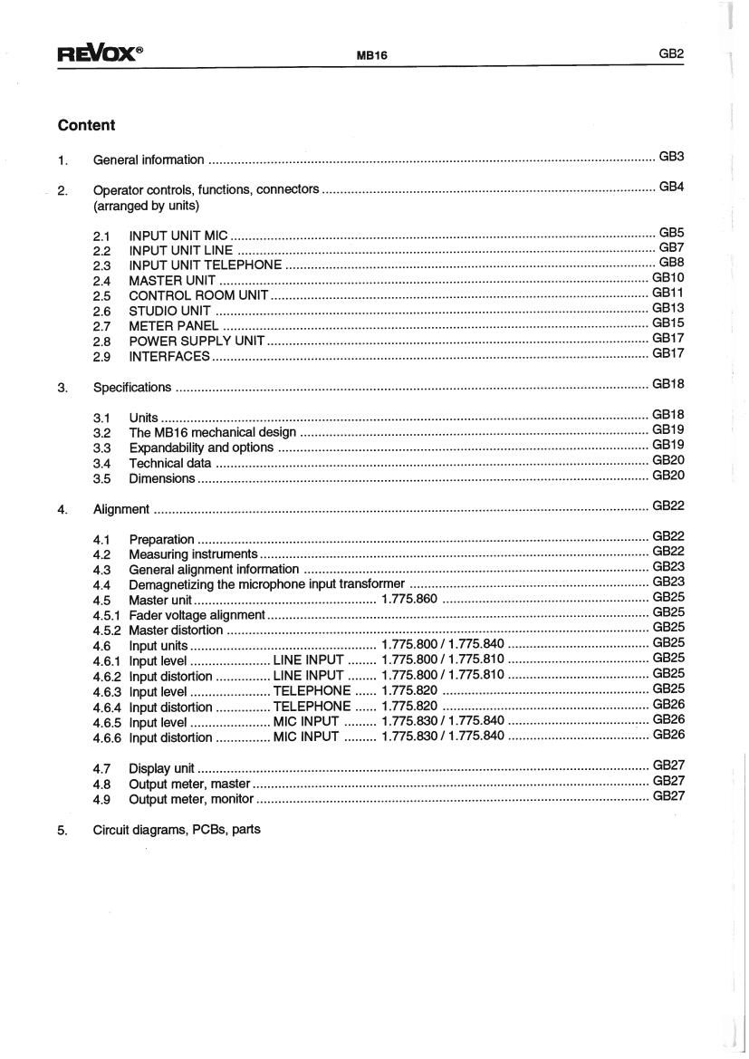
RWOXG M816 GB2


Content
1. General information ........................................................................................................................... GB3
2. Operator controls, functions, connectors ................................................................................
(arranged by units)
2.1 INPUT UNIT MIC....
2.2 INPUT UNIT LINE .........
2.3 INPUT UNIT TELEPHONE ..
2.4 MASTER UNIT .................
2.5 CONTROL ROOM UNIT ....................
2.6 STUDIO UNIT ...................................
2.7 METER PANEL ......
2.8 POWER SUPPLY UNIT.
2.9 INTERFACES ....................................
3. Specifications .................................................................................................................................. GB18
3.1 Units ............................................................
3.2 The MB16 mechanical design ..
3.3 Expandability and options
3.4 Technical data ...........
3.5 Dimensions ..................................................
4. Alignment ........................................................................................................................................ GB22
4.1 Preparation ..................................................
4.2 Measuring instruments ......
4.3 General alignment information
4.4 Demagnetizing the microphone input transformer ..
4.5 Master unit .................................................. 1.775.860
4.5.1 Fader voltage alignment.
4.5.2 Master distortion .....
4.6 Input units ............... 1.775.800/ 1.775.840 ..
4.6.1 Input level ..... LINE INPUT .. 1.775.800/ 1.775.810 ..
4.6.2 Input distortion . LINE INPUT .. 1.775.800/ 1.775.810
4.6.3 Input level ........ .TELEPHONE ...... 1.775.820 ......
4.6.4 Input distortion. TELEPHONE ...... 1.775.820
4.6.5 Input level ........ . MIC INPUT 1.775.830/ 1.775.840 ..
4.6.6 Input distortion ............... MIC INPUT .. 1.775.830/1.775.840 ............
4.7 Display unit ............................................................
4.8 Output meter, master.
4.9 Output meter, monitor ..........................
5.

Circuit diagrams, PCBs, parts

Page 2

G83 M816

1. General information

To help you find the operator controls and connectors
quickly, this instruction contains a fold-out page with a
general arrangement drawing of the M816.

On this drawing the units are identified with the
section number under which you will find a detailed
description and graphs.

A block diagram as well as PC layouts and
component lists can be found in Section 5, Diagrams.

REVDX6