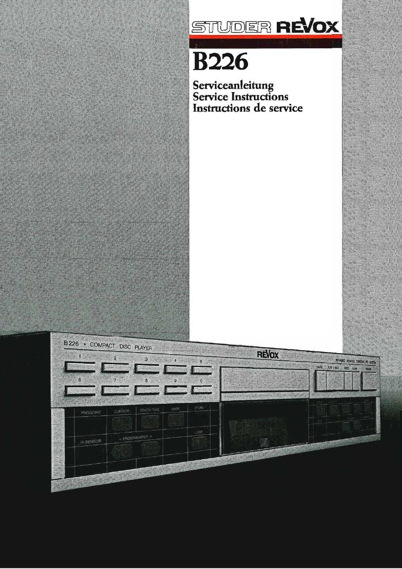
Revox B 226 Service Manual

This is the 123 pages manual for Revox B 226 Service Manual.
Read or download the pdf for free. If you want to contribute, please mail your pdfs to info@audioservicemanuals.com.

Page: 1 / 123
left right
Revox B 226 Service Manual

Extracted text from Revox B 226 Service Manual (Ocr-read)


Page 1

. f UCSTELJEJEIR REV xf
1 Serviceanleitung 7

Service Instructions
Instructions de service { ,


3226 ' COMPACT DISC, PLAYER

LE-hLL. ' a:
4.....1._I__L:_t

Page 2

Vorsicht:
Attention:
Warning:
Attenzione:
Precaucién:
Waarschuwing:
Advarsel:
Huomio:
Forsiktig:

'Varning:

Das Gerét ist in ausgeschaltetem Zustand (STANDBY) nicht von der Stromzufuhrung getrennt.

Cet appareil nest pas séparé du réseau lorsqu'll est déclenché (STANDBY),

This unit is not separated from the mains supply when swiiched off (STANDBY).

Ouesto apparecchio non é separate dalla rete quando l'mterruttore e spento (STANDBY),
ESTe aparato no esté separado de la red cuando esté apagado (STANDBY).

In uitgeschakelde toestand (STANDBY) is het apparaat niet gescheiden van de netspanning.
Apparaten er ogsaa hvis lukket (STANDBY) under stram.

Huolimatta s1ité, etta' virta on katkaistu Iaitteesta (STANDBY), swté ei ole eristetty séhkésta'.

Selvom stmmmen ikke er pa i apparatet (STANDBY), sa er det )kke skilt fra strgm.

Oaktat om strémmen ér avbruten i apparaten (STANDBY), sa ér den a'nda kopplad med strijm.

Page 40

STUIEELEJ HWOX 3226 E 2/5

2.5 ELECTRICAL ASSEMBLIES

2.5.1 Transformer

-> Fig. 2.9 / Fig. 2.10
I~Remove top cover (Section 2.2.1).
I Remove the CD hold doun clamp [24] by lightly pressing
doun on securing clips.
Important:
Do not Lose the nylon sleeve uith the O-ring on the
driving pin!
I Separate the following cable connections:
- Connecting cable [25] transformer -> DECODER PCB.
- Black ground Lead [26] on the bottom of the housing.
I Unfasten 2 screus [27] on the pouer inlet.
I Unfasten 4 screws [28] on the underside of the housing;
the transformer can now be pulled out of the unit
touards the back.

[26] [25]

Installation instruction:

I Make sure that the nylon sleeve on the driving pin 01
the hold-down clamp engages exactly into the guide
groove of the CD drauer.

Fig. 2.10
2.5.2 senvo PCB 1.769.400

-> Fig. 2.11

I Remove top cover (Section 2.2.1).

I Separate the following cable connections:
- Flat cable connection [29] SERVO PCB -> DECODER PCB '
- Cable connection [30] SERVO PCB -) KEYBOARD LEF1
-'Cable connection [31] SERVO PCB -> KEYBOARD RIGHT
- Cable connection [32] SERVO PCB -> LC DISPLAY
- Cable connection [33] SERVO PCB -> drauer motor
- Flat cable connection [31.] SERVO PCB -> play mechanism
(see Section 2.L.1).

I Unfasten 1 screH [35] and remove the driving lug.

I Unfasten the 1» screws [36] and pull the SERVO PCB back-
uard by approximately 10 mm.

I Pull the flat cable connection [3k] SERVO PCB -> play
mechanism through the opening in the drauer housing and
lay it flat across the circuit board.

I Careiully pull the SERVO PCB out of the unit towards the
back until the notch [37] (not aluays available) is
aligned Hith the rear panel of the housing.

I The circuit board can now be set upright and removed
from the unit.

2.5.3 DECODER PCB 1.769.420

-> Fig. 2.9 / Fig. 2.12
I Remove top cover (Section 2.2.1).
I Separate the following cable connections:
- Flat cable connection [38] DECODER PCB -> SERVO PCB
- Connecting cable [25] transformer -> DECODER PCB
- Cable connection [39] DECODER PCB -> headphones socket
- cable connection [A0] DECODER PCB -> ILLUMINATION
BOARD
I Uniasten 8 screws [1.1] and pull the DECODER PCB out
touards the top.