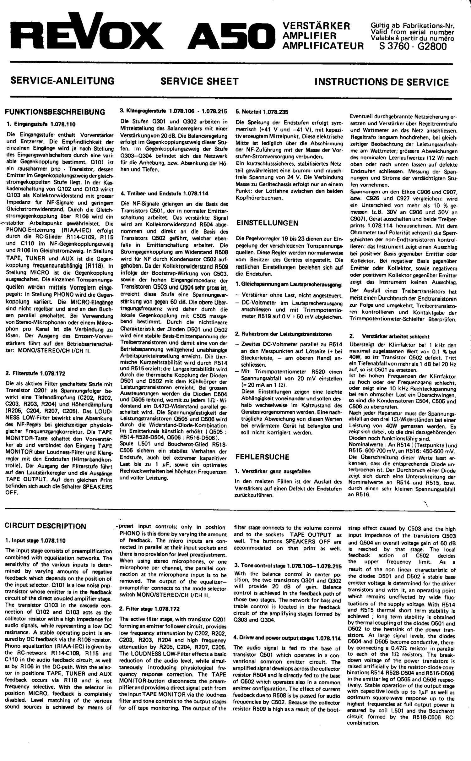
Revox A 50 Service Manual

This is the 5 pages manual for Revox A 50 Service Manual.
Read or download the pdf for free. If you want to contribute, please mail your pdfs to info@audioservicemanuals.com.

Page: 1 / 5
left right
Revox A 50 Service Manual

Extracted text from Revox A 50 Service Manual (Ocr-read)


Page 1

#Stflbiler

REV-X A50

AMPLIFIER

VERSTAR KER
AMPLIFICATEUR

Giiltig ab Fabrikations-Nr.
Valid from serial number
Valable a partir du numéro

S 3760 ~ G2800

SERVICE-ANLEITUNG

SERVICE SHEET

INSTRUCTIONS DE SERVICE

FUNKTIONSBESCHREIBUNG

1. Eingngsstufe 1.018.110

Die Eingangsstufe- enthalt Vorvarstiirker
und Entzerrer. Die Empfindlichkeit der
einzelnen Eingiinger wird ie nach Stellung
des Eingangswahlschalters durch eine vari»
able Gegenkcipplung bestimmt. 0101 ist
ein rauscharmer pnp . Transistor, dessen
Emitter im Gegenkcpplungszweig der gleich-
stromgekoppelten Stufe liegt. in der Kas-
kadenschaltung von 0102 und 0103 wirkt
0103 sis Kollektorwiderstand mit grosser
lmpedanz fiir NF~Signale und geringem
Gleichstromwiderstand. Durch die Gleich-
stromgegenkopplung iiber R106 wird ein
Arbeitspunkt gewohrleistet. Die
PHONO-Entzerrung lRlAA-IEC) erfolgt
durch die R0~Glieder 141140109, R115
und C110 im NF~Gegenkopplungszweig
und R106 im Gleichstromzweig. in Stellung

TAPE, TUNER und AUX ist die Gegen-
kopplung frequen-zu-nabhengig (R1181. In
Stellung MICRO ist die Gegenkopplung
ausgescha'ltet. Die einzelnen Tonspannungs-

quellen warden mitteis Vorreglern singe-
pegelt: in Stellung PHONO wird die Gegen-
kopplung variiert. Die MlCRO-Eing'ange
sind nicht regelbar und sind an den Buch-
sen parallel geschaltet. Bel Verwendung
von Stereo-Mikrophonen oder einem Mikro~
phon pro Kanal ist die Verbindung zu
Ibsen. Der Ausgang des Entzerr-Vorver-

stiirkers fiihrt auf den .Betriebsartenschai-
ter: MONO/STEREO/CH l/CH ll.

2. Filtmtufe 1.078.172

Die als aktives Filter geschaltete Stufe mit
Transistor 0201 als Spannungsfol'ger be-
wirkt eine Tiefendlimpfung (C202, R202,
0203, R203, R204) und Hdhendfimpfung
(R205, 0204, R207, 0205). Das LOUD-
NESS LOW-Filter bewirkt eine Absenkung
des NF-Pegels bei gleichzeitiger physiolo-
gischer Frequenzgangkor-rektur. Die TAPE
MONITOR-Taste schaltet den Vorverstar-
ker ab und verbindet den Eingang TAPE
MONITOR iiber Loudness-Filter und Klang»
regler mit den Endstufen li-linterbandkon-
trolls). Der Ausgang der Filters-tufts fiihrt
auf den Lautstiirkeregler und die Ausgiinge
TAPE OUTPUT. Auf dem glieichen Print

befinden sich auch die Schalter SPEAKERS
OF F.

3. Kimweglorstufo 1.078.106 - 1.078.215

Die Stufen 0301 und 0302 arbeiten in
Mitte'lstellung des Balanoereglers mit einer
Verstiirkung von 20 dB. Die Balanceregelung
erfolgt im Gegenkopplungszweig dieser Stu-
fen. lm Gegenkopplungszweig der Stufe
0303-0304 befindet sich das Netzvverk
fiir die Anhebung, bzw. Absenkung der H5-
hen und Tiefen.

4. Treiber' und Endstufe 1.0781 14

Die NF-Signaie gelangen an die Basis des
Transistors 0501, der in normaler Emitter-
schaltung arbeitet. Das verstiirkte Signal
wird am Kollektomiderstand R504 abge-
nommen und direkt an die Basis des
Transistors 0502 gefiihrt, welcher ebon-
falls in Emitterschaltung arbeitet. Die
Stromgegen-kopplung am Widerstand R508
wird fiir NF durch Kondensator C502 auf-

gehcben. 0a der Kollektorwiderstand R509
infolge der Bootstrap-Wirkung von 0503,
sowie der hohe-n Eingangsimpedanz der

Transistoren 0503 and 0504 sehr gross ist,
erreicht diese Stufe eine Spannungsver-

stiirkung von gegen 60 dB. Die obere Uber-
tragungsfrequenz wird daher durch die
lokale GegenkOpplung mit 0505 massge-
bend bestimmt. Durch die nichtlineare
Charakteristik der Dioden 0501 und D502
wird cine stabile Basis-Emitterspannung der
Treibertransistoren und damit eine von der
Betriebsspannung weitgehend unabhiingige
Arbeitspunkteinstellung erreicht. Die ther-
mische Kurzzeitstabilitat wird durch R514
und R515erzielt; die Langzeitstabilitiit wird
durch die thermische Kopplung der Dioden
0501 und 0502 mit dem Kiihlkorper der
Leistungstransistoren erreicht. Bei grossen
Aussteuerungen warden die Dioden D504
und 0505 leitend, womit zu jedem 152 - Wi-
derstand .ein 0.479-Widerstand parallel ge-
schaltet wird. Die Spannungsfestigkeit der
Leistungstransistoren 0505 und 0506 wird
durch die Widerstand-Diode-Kombination
im Emitterkreis kilnstlich erhoht ( 0505 :
R514R52B-0504, 0506 : R516-05061.
Spule L501 und BoucherotsGlied R518-
0506 sichem ein sta-biles Verhalten der
Endstufe, auch bei extremer kapazitiver
Last bis zu 1 uF, sowie ein optimales
Rechteckverhalten bei hochsten Frequenzen
und voller Leistung.

5. Neuteil 1.078.235

Die Speisung der Endstufen erfolgt sym-
metrisch (+41 V und -41 VI, mit kapazi-
tivv erzeugtem Mittelpunkt. Diese elektrische
Mitte ist lediglich iiber die Abschirmung
der NF~Zufiihrung mit der Masse der Vor-
stufen-Stromversorgung verbunden.

Ein kurzschlusssicheres, stabilisiertes Netz-
teil gewiihrleistet eine brumm- und rausch-
freie Spannung von 24 V. Die Verbindung
Masse zu Geriitechassis erfolgt nur an einem
Punkt: der Ldtfahne zvvischen den beiden
Kapfhorerbuchsen.

EINSTELLUNGEN

Die Pegelvorregler 19 bis 23 dienen zur Ein-
pegelung der verschiedenen Tonspannungs
quellen. Diese Regler werden normalerweise
vom Besitzer des Gerétes eingestellt. Die

restlichen Einstellungen beziehen sich aul
die Endstufen.

1. Gleiohspannung am Lautsprecherausgang:

- Verstarker ohne Last, nicht angesteuert.
- DC-Voltmeter am Lautsprecherausgang

anschliessen und mit Trimmpotentio-
meter R519 auf 0 V i 50 mV abgleichen.

2. Ruhestrom der Leistungstransistoren

-- Zweites DC-Voltmeter parallel zu R514
an den Messpunkten auf Lotseite l+ bei
Steckerleiste, - am oberen Randi an-
schliessen.

- Mit Trimmpotentiometer R520 einen

Spannungsabfall von 20 mV einstellen
(= 20 mA an 1 $2}.
Diese Einstellungen zeigen eine leichte
Abhéngigkeit voneinander und soilen des-
halb wechselweise im Kaltzustand des
Geriites vorgenomrnen warden. Eine nach-
triigliche Abweichung von diesen Werten
bei erwiirmtem Geréit ist belanglos und
soll nicht korrigiert warden.

FEHLERSUCHE

1. Verstfirker ganz ausgefallen

In den moisten Fallen ist der Ausfall des
Verstiirkers auf einen Defekt der Endstufen
zuriickzufiihren.

Eventuell durchgebrannte Netzsicherung er-
setzen und Verstarker iiber Regeltrenntrafo
und Wattmeter an das Netz anschliessen.
Regeltrafo langsam hochdrehen, bei gleich-
zeitiger Beobachtung der Leistungsaufnah-
me am Wattmeter; grossere Abweichungen
des nominalen Leerlaufwertes (12 W1 nach
oben oder nach unten lessen auf defekte
Endstufen schliessen. Messung der Span-
nungen und Strome der verdachtigten Stu-
fen vomehmen.

Spannungen an den Elkos C906 und 0907,
bzvv. 0926 und 0927 vergleichen: wird
ein Unterschied von mehr 31$ 10 % ge-
meesen (2.8. 30V an 0906 und 50V an
0907}, Gerat ausschalten und beide Treiber-
prints 1.078.114 herausnehmen. Mit dem
Ohmrneter lauf Polaritat achten!) die Sperr'
schichten der npn-Endtransistoren kontrol-
Iieren: das instrument zeigt einen Ausschlag
bei positiver Basis gegeniiber Emitter oder
Kollektor. Bei negativer Basis gegeniiber

Emitter odor Kollektor, sowie negativem
Oder positivem Kollektor gegeniiber Emitter
zeigt das Instrument keinen Ausschlag.

Der Ausfall eines Treibertransistors hat
meist einen Durchbruch der Endtransistoren
zur Folge und umgekehrt. Treibertransisto- 4
ran kontrollieren und Kontaktgabe der
Trimmmtentiometer-Schieifer iiberpriifen.

2. Versfirker arbeitet schlecht

Ubersteigt der Klirrfaktor bei 1 kHz den
maximal zugeiassenen Wert von 0.1 96 bei
40W, so ist Transistor 0502 defekt. Tritt
ein Tiefenabfall von mehrals 1 dB bei 20 Hz
auf, so ist 0501 zu ersetzen.

lst bei hohen Frequenzen der Klirrfaktor
zu hoch Oder der Frequenzgang schlecht,
oder zeigt eine 10 kHz-Rechteckspannung
bei rein ohmscher Last ein Ub'erschvvingen,
so sind die Kondensatoren 0504, 0505 und
cam zu fiberpriifen.

Nach jeder Reparatur muss der Spannungs-
abfall an den drei IQ-Widerstanden bei einer
Leistung von 40W gemessen werden. Es
zeigt sich dabei, ob die drei dazugehbrenden
Dioden noch funktionsfahig sind.
Nominalwerte : An R5141 (Testpunkte Iund
R515: 600700 mV, an R516: 450-500 mV.
Die Uberschreitung dieser Werte lasst er-
kennen, dass die entsprechende Diode un-
terbrochen ist. Der Durchbruch einer Diode
zeigt sich durch eine Unterschreitung der
Nominalwerte an R514 und R515, bzvv.

durch einen sehr kleinen Spannungsabfall
an R516.

"1»

1
s.

W

CIRCUIT DESCRIPTION

1. Input stem 1.078.110

The input stage consists of preamplification
combined with equalization networks. The
sensitivity of the various inputs is deter-
mined by varying amounts of negative
feedback which depends on the position of
the input selector. 0101 is a low noise pnp-
transistor whose emitter is in the feedback
circuit of the direct coupled amplifierr stage.
The transistor 0103 in the cascade con-
nection of 0102 and 0103 acts as the
collector resistor with a high impedance for
audio signals, while representing a low DC
resistance. A stable operating point is en-
sured by DC feedback via the R106 resistor.
Phono equalization (RIAA-IEC) is given by
the RC-network R114~0109, R115 and
0110 in the audio feedback circuit, as well
as by R106 in the DC-path. With the selec-
tor in positions TAPE, TUNER and AUX
feedback occurs via R118 and is not
frequency selective. With the selector in
position MICRO, feedback is completely
disabled. Level matching of the various
sound sources is achieved by means of

spreset input controls; only in position

PHONO is this done by varying the amount
of feedback. The micro inputs are con-
nected in parallel at their input sockets and
there is no provision for level preadjustment.
When using stereo micro-phones, or one
microphone per channel, the parallel con-
nection at the microohone input is to be
removed. The output of the equalizer-
preamplifier connects to the mode selector
switch MONO/STEREO/CH l/CH ll.

2. Filter stage 1.078.172

The active filter stage, with transistor 0201
forming an emitter follower circuit, provides
low frequency attenuation by 0202, R202,
0203, R203, R204 and high frequency
attenuation by R205, 0204, R207, C205.
The LOUDNESS LOW-Filter effects a basic
reduction of the audio level, while simul-
taneously introducing physiological fre-
quency response correction. The TAPE
MONlTOR~burton disconnects the pream-
plifier and providesa direct signal path from
the input TAPE MONITOR via the loudness
filter and tone controls to the output stages
for off tape monitoring. The output of the

filter stage connects to the volume control
and to the sockets TAPE OUTPUT as
well. The buttons SPEAKERS OFF are
accommodated on that print as well.

3. Tone control stage 1.078.1 064 £78.21 5

With the balance control in center po-
sition, the two transistors 0301 and 0302
will provide 20 dB of gain. Balance
control is achieved in the feedback path of
those two stages. The network for bass and
treble control is located in the feedback
circuit of the amplifying stages formed by
0303 and 0304.

4. Driver and power output stews 1 .078.114

The audio signal is fed to the base of
transistor 0501 which operates in a con-
ventional common emitter circuit. The
amplified signal develops across the collector
resistor R504 and is directly fed to the base
of 0502 which operates also in a common
emitter configuration. The effect of current
feedback due to R508 is by-passed for audio
frequencies by 0502. Because the collector
resistor R509 is high as a result of the boot.

strap effect caused by 0503 and the high
input impedance of the transistors 0503
and 0504 an overall voltage gain of 60 dB

is reached by that stage. The local
feedback action of 0502 decides
the upper frequency limit. As a

result of the non linear characteristic of
the diodes 0501 and 0502 a stable base
emitter voltage is determined for the driver
transistors and with it, an operating point
which remains unaffected by wide fluc-

tuations of the supply voltage. With R514
and R515 thermal short term stability is
achieved ; long term stability is obtained
by thermal coupling of the diodes 0.501 and
0502 to the heatsink of the power tran-
sistors. At large signal levels, the diodes
0504 and 0505 become conductive, there
by connecting a 0.4752 resistor in parallel
to each of the 1S} resistors. The break-
down voltage of the power transistors is
raised artificially by the resistor-diodecom-
binations R514-R528-D504 and R516-DSOG
in the emitter leg of 0505 and 0506 respec-
tively. Stable Operation of the output stage
with capacitive loads up to 1pF as well as
Optimum square-wave response up to the
big-lest frequencies at full output power is
ensured by coil L501 and the Boucherot

circuit formed by the R518-0506 RC-
combination.

Page 2

5. Power supply 1.078.235

Voltage supply to the output stages is
symmetrical (+41V and -41V), the null-
junction being formedby capacitors. The
0-volt point is connected to the common
line of the preamplifier supply via the shield
of the interconnecting audio frequency
cables only. A power supply with automatic
short circuit protection provides 24V free
from any ripple or noise interference. It is
connected to the amplifier chassis at one
point only: the solder tag between the two
headphone sockets.

ADJUSTMENTS

The trimmpotentiometers 19 to 23 are
intended for the matching of levels from
various sound sources. As a rule, they will
be adjusted by the user. All remaining
adjustments refer to the power output

£18905.

1. DC voltage at the speaker terminals:

- amplifier without load, no audio signal.

- connect DC-voltmeter to the loudspeaker
terminals. Adjust trimmpotentiometer
8519 to read 0V 1 somv.

DESCRIPTION DU SCHEMA

1. EW d'entrbe 1.078.110

L'étage d'entree est un preamplificateur-
correcteur; la sensibilité des dlfférentcs
entrees est determines par une contra-
réaction variable salon la position du 96-
Iecteur d'entrée. 0101 est un pnp a tres
faible souffle dont l'emetteur se trouve dans
le circuit de contra-reaction de l'etage a
liaison directs. 0102 at 0103 sont montes
en cascade, at 0103 tient lieu de resistance
de collecteur, qui presents une forte impe-
dance aux signaux BF en meme temps
quun faible resistance on courant continu.
La centre-reaction en courant continu ob-
tenua par 8106 contribue a la stabilisation
du point de travail. En position PHONO,
la correction (8lAA-lEC) est obtenue par
linsertion des circuits 8114-0109, 8115 at
0110 dans la boucle de contrasréaction.
En position TAPE, TUNER at AUX la
centre-reaction per 8118 est independents
de la frequence, alors quen position M 1080
elle est annulee. Le niveau dos differentes
sources sonores est aiusté par les potentio-
metresde préréglage; pour l'entree PHONO,
il y a modification de la contra-reaction.
Les entrees MICRO ne sont pas raglables et
sont reliees entre elles aux homes; en ces
d'utilisetion dun microphone stéréo,.couper
la connexion. La sortie du préamplificateur-
correctaur aboutit au selecteur de mode
MONO/STEREO/CH l/CH ll.

2. Eng! dos filtre: 1.078.172

L'etage component 0201 an émetteur
follower est un filtre actif qui provoque
une attenuation dos frequences graves (par
0202, 8202, 0203, 8203, 82041 et des
fréquences aigues (per 8205, C204, 8207,
0205). Le filtre LOUDNESS LOW pro-
voque une balm du niveau BF avec cor-
rection physioIOgique de la courbe do
reponse. La touche TAPE MONITOR d6-
connecte la préamplificeteur et relie di-
rectement lentree TAPE MONITOR aux
étages correcteurs de tonalite icontrbie de
I'enregistrement en cours). La sortie de
l'étage des filtres aboutit aux prises TAPE
OUTPUT et au potentiometre de volume.
La plaquette oomporte egalement une
touche SPEAKERS OFF dc deconnexion
des haut-parleurs.

2. miescent current of power transistors:

- connect a second DC-voitmeter across
8514 at the test points on the soldered
side (+at the connector, -at the upper
edge).

- adjust for a voltage drOp of 20 mV
(=20 mA on 1 $2) with trimmpotentio-
meter 8520.

Since there is a slight interaction between
the above two adjustments, they should
be repeated alternatively prior to warm-
up of the equipment. A later deviation
from these values, after the amplifier has
reached operating temperature, is of no
consequence and must not be corrected.

TROUBLE SHOOTING

1. Amplifier inoperative
If the amplifier is completely inoperative,
this will in most cases be due to a defect in

the power output stages.

Check power fuse and replace if necessary.
Connect amplifierto the power line via a con-
tinuously variable transformer and watt-
meter. Slowly increase the supply voltage
by means of the variable transformer and
observe power consumption: an appreciable

3. Etage correcteur de tonelite 1.078.106 at
1.078.215

Avec le potentiometre dc balance en po-
sition médiane, 0301 at 0302 amplifient
les signaux d'environ 20 dB; le rég-Iage de la
balance se felt an modifiant Ia contra-
réaction de l'étage. Un réseau d'éléments
réactifs est incorporé dans la boucle de
contra-reaction de l'étage 0303-0304 at
provoque l'atténuation ou le relévement
dos bosses et des aigués.

4. Etage driver at de puimnce 1.078.114

Le signal BF est applique a la base de 0501,
monté en émetteur common; la contre-
resetion en courant due s 8508 est éliminée
per 0502 pour les signaux BF. La resistance
de collecteur 8509 deviant tres grande,

grace a Ieffet de bootstrap do 0503 et a la
forte impedance dentrée des transistors
0503 8t 0504, et iampiificetion en tension
atteint 60 dB. La contre~réaction locale due
a 0505 determine la fréquence supérieure
de transmission. Grace is Ieur caracteristique
non linéaire, les diodes 0501 at 0502
determinant la tension baseemetteur des
drivers, et le point de travail est pratique-
ment independent de la tension de service.
La stabilité thermique a court terme est
obtenue per 8514 at 8515 ; la stabilité a
long terms resulte du couplage thermique
entre les diodes 0501 at 0502 et le radia-
teur des transistors dc puissance. Lorsque
les signaux ont une grande amplitude, les
diodes 0504 at 0505 deviennent conductri-
cos, mettant en parallels une resistance de
0,4752 sur cheque resistance de 152. La re-
sistance au claquage des transistors de
puissance 0505 at 0506 est augmentée
artificiallement par l'insertion dc circuits
resistance-diode dans les emetteurs i pour
0505 ; 8514-8528-0504, pour 0506 :
8516-05061.

La bobine L501 et la circuit Boucherot
8518-0506 assurent la stabilité de i'étage,
meme avec one charge capacitive allant
jusqu'a 1 uF, et améliorent la réponse aux
signaux carrés de fréquence éievée, a la
puissance maximum.

5. Alimentation 1.078.235

Les stages de puissance sont alimentés
syrnétriques (HIV at -41Vl, avec point
milieu determine par capacité. Ce point
0V n'est relié a la masse de I'alirneneation
des etages precedents qua par le blindage
du cable de liaison BF.

up or down variation from the nominal
power consumption 112W) under no signal
condition points to a defective power out-
put stage. Measure voltages and currents in
the suspected amplifier stages. Compare
voltages on the electrolytic capacitors 0906/
0907 and 0926/0927 respectively. if this
reveals a discrepancy of more than 10 96
ie.g. 30V on 0906 and 50V on 0907) turn
amplifier off and remove both driver boards
1.078.114. Check the junctions of the npn-
power transistors with the use of an ohm-
meter (observe polarity: the meter will
show a deflection with the base positive
against emitter or collector. With a negative
base against emitter or collector, as well as
with a negative or positive collector against
the emitter, the meter will show no deflec-
tion. The break-down of a driver transistor
will in most cases result in the break-down
of a power transistor as well, or vice-verse.
Check the driver transistors and make sure
that the wiper of any of the trimmpotentio-

meters makes good electrical contact.

2. Amplifier worlts unmisfactorily

If the distortion figure at 1kHz is higher
than the rated value of 0.1 % at an output

Un étage d'alimentation protege contre les
court-circuits fournit one tension stabilisée
dc 24V, sans ronflement et sans souffle; la
liaison entre la masse et le chassis se fait
uniquement par la cosse qui se trouve
entre les deux prises pour casque stereo.

REGLAGES

Les potentiometres ajustables 19 a 23,
prévus pour Ie preréglage des différentes
sources de signaux, sont réglés en principe
lors de la mise on service par I'usager; les
souls autres réglages concernent les étages
de puissance.

1. Tension continue a la sortie bout-parlour:

L'amplificateur ne recevant aucun signal
B F et la charge étant déconnectée, raccorder
un voltmetre continu a la sortie haut-
parlour; régler le potentiométre 8519 de
facon a obtenir 0V :t 50 mV.

2. Courant de rapes des transistors do
puissenoe:

Connector un second voltmetre continu
aux bornes de 8514, par les cosses
accessibles ecte soudures (+ pres du connec-
teur, - au bord superieurl: ajuster 8520
pour obtenir 20 mV (=20 mA dens 10}.
Gas deux reglages sont quelque peu inter-
dépendants et doivent etre- effectués alter-
nativement, l'amplificateur étant froid. Una
variation ultérieure de cette valeur, Iorsque
l'appareil est chaud, est sans importance at
no doit pas etre corrigee.

DEPAN NAG E

1. Penna totals:

Dans la plupart des ces, les pannes dc
lamplificateur sont dues a one défectuosité
des étages de puissance. 8emplacer is ces
échéant 1e fusible do réseau sauté et raccor-
der Iappareii au reseau s travers on transfer-
mateur réglable et un wattmetre; mattre
progressivement sous tension at observer
la consommation. Une difference impor-
tente, en plus ou en moins, par rapport a la
valeur nominale a vide (12W), est I'indice
d'une défectuosité dans les éteges de
puissance. Procéder ala mesure des courants

of 40W, the transistor 0502 is defective.
Capacitor 0501 has to be replaced if a loss
of low frequencies in excess of 1 dB at
20 Hz is measured.

Too high a distortion factor at high
frequencies, or poor frequency response as
well as a tendency of overshoot when
applying a 10 kl-iz square wave' with a
purely resistive load at the output, indi-
cates the necessity to check the capacitors
0504. 0505 and 0506.

After each repair it is hmry to mea-
sure the voltage dr0p across the three 10
resistors while driving the amplifier to an
output of 40W. This will show whether or

not the three associated diodes are still
functional.

Nominal values : across 8514 (test points)
and 8515 : 600 to 700 mV, across 8516 :
450 to 500 mV. Any excess voltage indi-
cates an open circuit condition in the
corresponding diode. A short circuit condi-
tion in a diode results in voltage reading
which is lower than the nominal value

across 8514 and 8515, or in a very low
voltage drop across 8516.

et des tensions dans les etages suspectés.
Mesurer Ia tension aux borne: des conden-
sateurs electrolytiques 0906 at 0907, puis
0926 at 0927. Si la tension differs de
plus de 10 96 (par example 30V sur 0906
at 50V sur 0907i, cooper l'alimentation at
retirer les plaquettes des étages drivers
(1.078.114).Vérifier s l'ohmmetre (atten-
tion s la polarité) les junctions des transis-
tors npn de puissance: il y a conduction si
la base est positive par rapport s l'emetteur
ou au collecteur; il n'y a pas conduction si
la base est negative par rapport s l'émetteur
ou au collecteur, ni dens aucun sens entre
I'émetteur et la collecteur.

La ciaquage d'un transistor driver provoque
tres souvent le claquage des transistors de
puissance, at inversement: verifier les dri~
vers. Examiner les potentiometres ajusta-
bias: le curseur doit faire bon contact avec
la couche résistante.

2. Mauvais fonctionnement:

Si Ie taux de distension a 1 kHz depasse la
valeur maximum admissible de 0.1% a 40W.
la transistor 0502 est defectueux. Si Iatte-
nuation des frequences graves depane 1 dB
s 20 Hz, remplacer 0501.

Si la courbe'de réponse est deficiente ou la
distorsion trop importante aux fréquences
aigués, ou si on signal carre de 10 kHz a
tendence a surosciller avec one charge
purement ohmique, verifier les condense.
tours 0504, 0505 at 0505.

Apres cheque reparation, il faut mesurer la
tension aux bornes des trois resistances de
10, a la pui-ssance do 40W, afin de contrbler
I'état des diodes oorrespondantes.

Valeurs nominaies : 8514 i cusses ) at
8515 : 600 a 700 mV, 8516 : 450 s
500 mV. Lorsqu'il y a depassement de ces
vaieurs, la diode correspondents est coupee ;
si la tension est inferieure a la valeur nomi-
nele aux homes do 8514 at 8515, DU 5
peine mesurable aux bornes do 8516, la
diode correspondents est claquee.